Sign In
Upload
Manuals
Brands
MAXA Manuals
Air Conditioner
i-32V5C MIDI 0121
MAXA i-32V5C MIDI 0121 Air Conditioner Manuals
Manuals and User Guides for MAXA i-32V5C MIDI 0121 Air Conditioner. We have
3
MAXA i-32V5C MIDI 0121 Air Conditioner manuals available for free PDF download: Installation Manual, Technical Bulletin, Manual
MAXA i-32V5C MIDI 0121 Manual (36 pages)
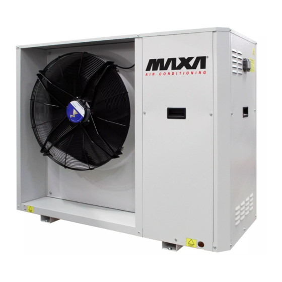
Chillers and Inverter Air/Water heat pumps with axial fan
Brand:
MAXA
| Category:
Chiller
| Size: 2 MB
Table of Contents
Table of Contents
3
Purpose and Content of the Manual
6
How to Keep the Manual
6
Graphic Symbols Used in the Manual
6
Permitted Use
6
General Safety Guidelines
6
Personal Protective Equipment
7
Workers' Health and Safety
7
Safety Signals
7
Refrigerant Safety Data Sheet
7
User Interface - Controller
7
Display
8
Keys
8
Led
8
Menu
9
SETPOINT MENU [Set]
9
Password Menu [Pss]
9
ALARMS MENU [Err]
9
PROBES MENU [Tp]
9
DIGITAL INPUTS MENU [ID]
10
PARAMETERS MENU [Par]
10
OPERATING HOURS MENU [Ohr]
10
LOG MENU [Hist]
10
FIRWARE VERSION MENU [Fir]
10
Usb Menu[Usb]
10
FIRMWARE UPDATE [Updf]
10
Parameters Update [Uppa]
10
System Resources
11
Editing Dynamic Set-Point
11
Set-Point Modification from Analogue Input
12
Circulator
12
Continuous Operation
13
Operation on Call by Temperature Controller
13
Operating on Call by Temperature Controller with Periodic Activation
13
Operation with Integration Resistor Active
13
Antifreeze Hydraulic Pump Operation
13
Proportional Regulation
13
System Venting
14
Compressor On/Off Logic
14
Regulation in Cooling Mode
14
Regulation in Heat Mode
15
Fan
15
Silenced Ventilation
15
Compressor Crankcase Resistence
15
Enabling Domestic Hot Water Production
15
Memorising the Probe in Heating Mode
16
Heating Mode on Dhw Storage Tank
16
Remote Function
16
On/Off
16
Summer/Winter Mode Change
16
Dhw Call from Digital Input
17
System Water Remote Probe
17
Defrosting Cycle
17
Double Set-Point
17
Minimum Hz Functions
17
Minimum Hz Functions
18
Auxiliary Resistances
18
System Resistance
18
Sanitary Resistance
18
Individual System/Health Integration Resistence
18
Integration Resistance Selection Mode
19
Circulator Management with Active Resistance
19
Boiler Enabling
19
Logic of Integration Heaters And/Or Boiler in Joint Operation or in Sub- Stitution of the Heat Pump Compressor
19
Operation Heat Pump Mode
20
Joint Operation (I Bracket)
20
Joint Operation (II Bracket)
20
Operation in Substitution
20
Operating Bands
21
Auxiliary Systems Offset Management
23
Antifreeze Protection Resistances (if Ka Accessory Is Present)
24
Partial Recovery with Desuperheater (if Ds Accessory Is Present)
24
Logics that Can be Activated with Gi Module - System Management (Accesso- Ry)
24
Permitted Configuration Tables
24
Alarms
27
E006] Flow Switch
27
E018] High Temperature
27
E005] Antifreeze
27
E611÷E681] Probe Alarms or Pressostat
27
E691÷E701] Transducer Alarms
28
E801] Inverter Timeout
28
E851 ÷E971] Inverter Alarms
28
E00] Remote On/Off Signalling
28
E001] High Pressure
28
E002] Low Pressure
28
E008] Driver Limitation
28
E041] 4-Way Valve
28
E042] Domestic Hot Water Sanitary
28
Advertisement
MAXA i-32V5C MIDI 0121 Installation Manual (44 pages)
Chiller and Inverter Air/Water heat pumps with axial fan
Brand:
MAXA
| Category:
Chiller
| Size: 9 MB
Table of Contents
Table of Contents
3
Purpose and Contents of the Manual
5
How to Keep the Manual
5
Graphic Symbols Used in the Manual
5
Normative References
5
Permitted Use
6
General Safety Guidelines
6
Workers' Health and Safety
7
Personal Protective Equipment
7
Safety Signs
8
Specific R32 Gas Warnings
10
R32 Gas Charge
10
R32 Gas Disposal
10
Safety Rules for R32 Gas Transport and Storage
10
Installation
10
General
10
Transport and Storage Limit Temperature
11
Lifting and Handling
11
Lifting Mode
11
Positioning and Minimum Technical Clearances
12
Dimensions
14
Model I-32V5C MIDI 0121, I-32V5C MIDI 0126
14
Model I-32V5H MIDI 0121, I-32V5H MIDI 0126
14
Model I-32V5C MIDI 0128, I-32V5C MIDI 0132
15
Model I-32V5H MIDI 0128, I-32V5H MIDI 0132
15
Barycentre and Dampers Location
15
Accessing the Inner Parts
16
Costumised Chapters for each Series
16
Plumbing Connections
17
Features of the Circuit Water
17
Hydraulic Diagram Inside the Unit
18
Drainage System
18
Filling / Discharge of the Plant
19
Service Sleeves
20
Electrical Connections
20
Access to Electric Panel
20
Power Supply
21
User Terminal Block
22
Control Logics
23
Fuses
23
Functional Diagrams
24
I-32V5C MIDI
24
I-32V5H MIDI
25
Startup
26
Switching on the Unit
26
Instructions for the User
26
Shutdowns for Long Periods
26
Maintenance and Periodic Checks
27
Cleaning the Finned Coil
28
Cleaning the Filled Coil Treated with the Anti-Corrosion Method
28
Cleaning of External Surfaces
29
Extraordinary Maintence
29
Decommissioning
29
Residual Risk
30
Technical Data
34
TECHICAL SHEET I-32V5C MIDI
34
TECHNIICAL SHEET I-32V5H MIDI
35
Unit and Auxiliary Electrical Data
36
Operating Limits
36
Evaporator Water Flow Rate
36
Cold Water Production (Summer Mode)
36
Hot Water Production (Summer Mode)
36
Ambient Air Temperature and Summerised Table
36
User Interface - Controller
38
Menu
39
Setpoint Menu
39
ALARM Menu[Err]
40
Troubleshooting
40
MAXA i-32V5C MIDI 0121 Technical Bulletin (36 pages)
Brand:
MAXA
| Category:
Air Conditioner
| Size: 2 MB
Table of Contents
Table of Contents
3
Description of Unit and Technical Specifications
5
Framework
5
Compressors
5
Air Side Heat Exchanger
5
Utility Side Heat Exchanger
5
Fan
5
Cooling Circuit
5
Electrical and Control Panel
6
Control and Protective Devices
7
Water Circuit
7
Description of Versions and Accessories
7
Versions
7
List of Accessories
7
Description of Accessories
8
Factory-Fitted Standard Components
8
Factory-Fitted Optional Accessories
9
Standard Components Supplied Separately/Activatable after Delivery
9
Optional Accessories Supplied Separately/Activatable after Delivery
9
Installation
10
Unit Dimensions,Hydraulic Connections,Weights and Centre of Gravity Position
10
Net Dimensions and with Packaging
10
Detail of Connections and Location
11
Weights
11
Location of the Centre of Gravity and Vibrations Dampers
11
Technical Service Areas
12
Hydraulic Circuit
14
System Water Specifications
15
Typical Hydraulic Scheme
15
Hydraulic Diagram Inside the Unit
16
Minimum Water Content and Hydraulic Circuit Volumes
17
Condansate Drainage System
17
System Charging / Discharging
17
Air Vent Valve
18
Technical Data
19
Chiller Data Sheet
19
Data Sheet for Desuperheater Unit
20
Unit and Auxiliary Electrical Data
21
Corrective Factors
21
Correction Factors for Use of Water-Glycol Mixture
21
Scaling Correction Factors
21
Calibrations and Protections Controls
21
Correction Factors Depending on Altitude
22
Hydronic Group Data
23
Useful Head
23
Pressure Drop Y-Filter Accessories
23
Circulator /Pump Curves
24
Noise Level
25
Powers and Sound Pressures Standard Version
25
POWERS and SOUND PRESSURES Sl VERSION
25
Operating Limits
26
Water Flow Rate at the Evaporator
26
Chilled Water Production (Summer Operation)
26
Ambient Air Temperature and Summary Table
26
Performance Table
28
Cooling Standard Version
28
Cooling Bt Version
28
Eer Values for Calculating the Energy Performance of Buildings Accord- Ing to Uni/Ts 11300-3
30
Model I-32V5 MIDI 0121
30
Model I-32V5 MIDI 0126
30
Model I-32V5 MIDI 0128
31
Model I-32V5 MIDI 0132
31
Refrigerant Safety Data Sheet
32
Advertisement
Advertisement
Related Products
MAXA i-SHWAK V4
MAXA i-32V5H MIDI 0121
MAXA i-32V504
MAXA i-32V506
MAXA i-32V5SL08
MAXA i-32V510
MAXA i-32V512
MAXA i-32V5SL12T
MAXA i-32V514
MAXA i-32V5SL16T
MAXA Categories
Air Conditioner
Inverter
Chiller
Heat Pump
Heating System
More MAXA Manuals
Login
Sign In
OR
Sign in with Facebook
Sign in with Google
Upload manual
Upload from disk
Upload from URL