Sign In
Upload
Manuals
Brands
masibus Manuals
GPS
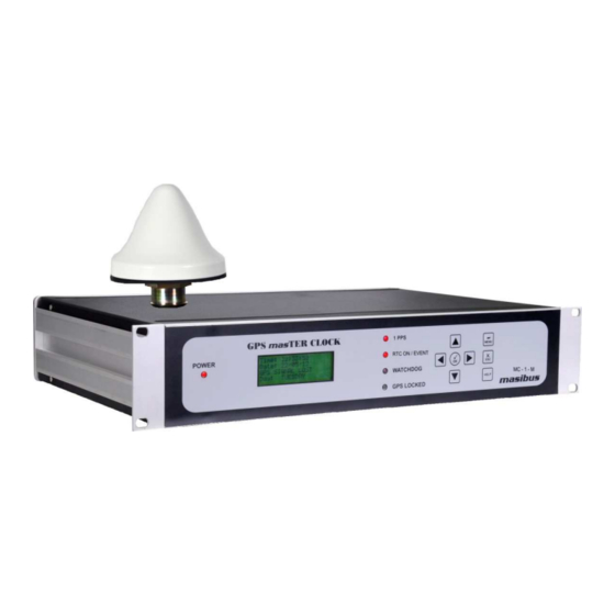
GPS MASTER CLOCK MC-1-M
masibus GPS MASTER CLOCK MC-1-M Manuals
Manuals and User Guides for masibus GPS MASTER CLOCK MC-1-M. We have
1
masibus GPS MASTER CLOCK MC-1-M manual available for free PDF download: User Manual
masibus GPS MASTER CLOCK MC-1-M User Manual (103 pages)
Brand:
masibus
| Category:
GPS
| Size: 4 MB
Table of Contents
Table of Contents
3
1 Unpacking GPS Master Clock Model MC-1
8
Standard Items
8
Optional Items
8
2 Introduction
9
3 GPS Fundamentals
10
The Basis of GPS
10
4 GPS Specification
12
GPS Master Clock Model MC-1-M Model
12
Issue no
14
Mechanical Dimensions Layout
17
GPS Master Clock Model MC-1-M Mechanical Dimensions
17
5 Unit Front and Rear Panel Description
18
GPS Master Clock Front Panel
18
GPS Master Clock Model MC-1-M Front Panel Description
18
GPS Master Clock Rear Panel
19
GPS Master Clock Model MC-1-M Rear Panel Description
19
GPS Master Clock Model MC-1-M Front Panel Key Definitions
19
Power Supply Terminal
20
Relay and Standard Event Terminal
20
Additional Events Terminal
20
GPS Ethernet NTP Terminal
20
1PPS BNC Terminal
21
IRIG-TTL, am BNC Terminal
21
COM1 Terminal
21
COM2 Terminal
22
GPS Antenna Terminal
22
6 GPS Master Clock Model MC-1-M Installation
24
GPS Antenna Installation
25
Mounting the Antenna
26
Antenna Mounting
26
Antenna Mounting with Lightening Arrestor
26
Verifying Antenna and Cable Operation
28
Checking the Antenna Voltage
28
Power Supply Check
28
Checking the Antenna Resistance
28
Antenna Surge Suppressor
29
Technical Details on GPS Antennas and Cable
29
Unit Installation
30
Antenna Mounting
30
Wiring Diagram
31
GPS Master Clock Model MC-1-M Wiring Diagram
31
7 Hardware Jumper Setting
32
Relay Contact Output Configurations
33
POWER Relay Contacts
33
GPS Master Clock Model MC-1-M Main Board (Top View)
33
Power Relay Configuration
33
GPS LOST Relay Contacts
34
WATCHDOG Relay Contacts
34
COM1 Terminal RS232 / RS485 Output Configurations
34
GPS LOST Relay Configuration
34
WATCHDOG Relay Configuration
34
COM2 Terminal RS232 / RS485 Output Configurations
35
COM1 Terminal RS-232/RS-485 Configuration
35
COM2 Terminal RS-232/RS-485 Configuration
35
8 GPS Master Clock Model MC-1-M Power on
36
Receiver Boot-Up Mode
36
Battery Backup RTC and GPS Receiver RAM Configurations
37
Startup Operation
37
Basic Normal Run Mode Operation
39
9 Unit Setup Configuration
42
Front Panel Keypad Layout
42
10 Serial Communication and Configuration
45
Serial Port Setup and Serial Cable Configuration
45
Path of Hyperterminal
45
Hyperterminal View
46
LCD Display - COM Port Settings of GPS Master Clock
47
Hyperterminal Configuration
47
Configuration Commands
48
General Commands
48
Serial Message - Configuration Menu
50
Serial Message - Help Menu
51
Communication Commands
52
Hyperterminal Communication Settings
53
Time Zone Offset Commands
54
LCD Display Parameters Commands
55
COM2 Serial Time Frame Command
56
Event Command
56
Additional Event's Command
56
Ethernet Default Command
57
Password Change Command
58
SNMP Default Command Parameters
58
Miscellaneous Command
59
Default Command Parameters
59
Antenna Cable Propagation Delay Command
60
Manual Time Setting Command
60
Example to Illustrate Unit Commands
62
11 Timing Outputs - Serial, IRIG-B / IEEE 1344, NTP
65
Timing Output - Serial
65
NMEA-0183 RMC Time Frame Output
65
T-Format Time Frame Output
65
NMEA-0183 Time String Format
65
NGTS Time Frame Output
66
T-Format Time String Format
66
Timing Output - IRIG-B / IEEE 1344 C37.118-2005
67
Introduction
67
Time Code Output
67
NGTS Time String Format
67
Standard IRIG-B Output
68
Abstract of IRIG-B Time Code
68
IRIG-B am & IRIG-B DCLS Signals
68
IRIG-B IEEE 1344 Extension
69
IRIG-B Waveforms
69
Generated IRIG-B Time Codes
70
Selection/Configuration of IRIG-B Time Codes
70
Connecting IRIG-B Time Code
71
Connecting IRIG-B DCLS
72
Connecting IRIG-B am
72
Timing Output - NTP
72
NTP Introduction
72
GPS Master Clock NTP Output
73
NTP Frame Format
73
NTP Client Synchronization
74
NTP Hierarchical Time Distribution
75
12 Relay and Pulse Outputs
78
Relay Contact Outputs
78
Relay Contact Status Chart During Operation
78
Pulse Outputs
79
1PPS Output
79
Event Output (PPM/PPH)
79
Additional Event Outputs (Programmable Pulse Outputs)
79
13 Ethernet Communications: Telnet, SNMP
80
Telnet
80
Configurable Parameters through Telnet
80
Snmp
81
SNMP Addressing
81
Protocol Detail
81
SNMP Operation
82
SNMP Traps
87
14 Holdover Mode
89
15 Options
90
Optional Input Power Supply
90
Option 1: AC/DC Power Input
90
Option 2: DC Power Input
90
Optional Module - 1PPS Output
91
Specifications
91
Optional Module - IRIG-B TTL
91
Optional Module - IRIG-B am
91
Optional Module - NMEA Output
92
Specifications
92
Switch Configuration for Optional NMEA Module
92
Baudrate Switch Settings for Optional NMEA Module
93
Parity Switch Settings for Optional NMEA Module
93
Stopbit Switch Settings for Optional NMEA Module
93
Databits Switch Settings for Optional NMEA Module
93
Optional Module - NTP Output
94
Specifications
94
Optional Module - PTP/IEEE-1588 Output
95
16 Appendix List
96
17 Troubleshooting
97
18 Abbreviations
102
Advertisement
Advertisement
Related Products
Masibus masTER T-Sync MTS200
Masibus MC-1-DE
Masibus MC-1-DH
Masibus MINT Series
Masibus MINT-DI-16
Masibus MINT-DO-16
Masibus MINT-AI-08
Masibus MINT-AOI-08
Masibus MINT-AOV-08
masibus Categories
Controller
Touch Panel
Transmitter
Test Equipment
Measuring Instruments
More masibus Manuals
Login
Sign In
OR
Sign in with Facebook
Sign in with Google
Upload manual
Upload from disk
Upload from URL