Sign In
Upload
Manuals
Brands
Mannesmann Manuals
DC Drives
ecodrive03
Mannesmann ecodrive03 Drive Controller Manuals
Manuals and User Guides for Mannesmann ecodrive03 Drive Controller. We have
1
Mannesmann ecodrive03 Drive Controller manual available for free PDF download: Troubleshooting Manual
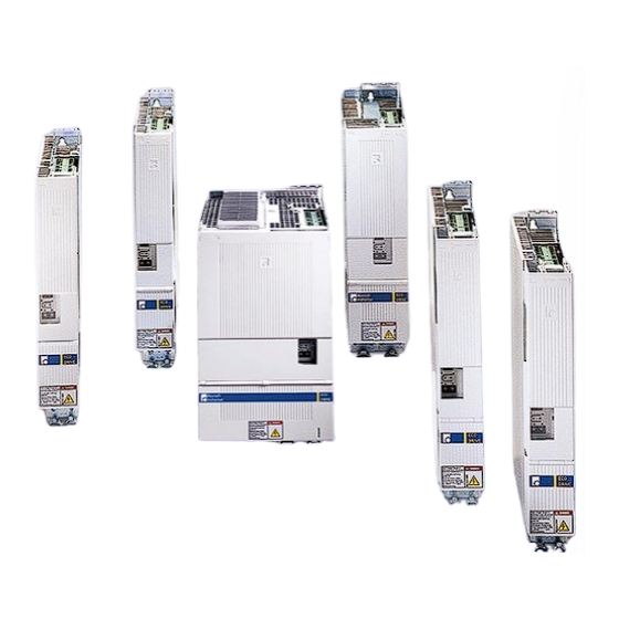
Mannesmann ecodrive03 Troubleshooting Manual (128 pages)
drive for machine tool application with SERCOS-, Analog- and Parallelinterface
Brand:
Mannesmann
| Category:
DC Drives
| Size: 1 MB
Table of Contents
Table of Contents
5
1 Diagnostic Message Descriptions
13
Overview of the Diagnostic Message Descriptions
13
Diagnostic Message Types
13
Construction of a Diagnostic Message
13
2 Safety Instructions for Electric Servo Drives and Controls
17
Introduction
17
Explanations
17
Hazards by Inappropriate Use
18
General Information
19
Protection against Contact with Electrical Parts
20
Protection by Protective Low Voltage (PELV) against Electrical Shock
21
Protection against Dangerous Movements
22
Protection against Magnetic and Electromagnetic Fields During Operations and Mounting
24
Protection against Contact with Hot Parts
24
2.10 Protection During Handling and Installation
25
2.11 Battery Safety
25
2.12 Protection against Pressurized Systems
26
3 Description of Diagnostic Letters F
27
Error Diagnostic Messages F
27
F207 Switching to Uninitialized Operation Mode
28
F208 UL the Motor Type Has Changed
28
F209 PL Load Parameter Default Values
29
F218 Amplifier Overtemp. Shutdown
29
F219 Motor Overtemp. Shutdown
30
F220 Bleeder Overload Shutdown
30
F221 Motor Temp. Surveillance Defective
31
F223 Error During Initialisation of the Parking Axis
31
F224 Maximum Braking Time Exceeded
32
F226 Undervoltage in Power Section
32
F228 Excessive Deviation
33
F229 Encoder 1 Failure: Quadrant Error
33
F230 Max. Signal Frequency of Encoder 1 Exceeded
33
F236 Excessive Position Feedback Difference
34
F237 Excessive Position Command Difference
35
F242 Encoder 2 Failure: Signal Amplitude Wrong
35
F245 Encoder 2 Failure: Quadrant Error
36
F246 Max Signal Frequency of Encoder 2 Exceeded
37
F248 Low Battery Voltage
37
F253 Incr. Encoder Emulator: Pulse Frequency too High
38
F260 Command Current Limit Shutoff
38
F262 External Short at Status Outputs
38
F267 Erroneous Internal Hardware Synchronization
39
F269 Error During Release of the Motor Holding Brake
39
F276 Absolute Encoder out of Allowed Window
40
F277 Current Measurement Trim Wrong
40
F281 Mains Fault
41
F386 no Ready Signal from Supply Module
41
F401 Double MST Failure Shutdown
41
F402 Double MDT Failure Shutdown
42
F403 Invalid Communication Phase Shutdown
42
F404 Error During Phase Progression
42
F405 Error During Phase Regression
43
F406 Phase Switching Without Ready Signal
43
F434 Emergency-Stop
43
F629 Positive Travel Limit Exceeded
43
F630 Negative Travel Limit Exceeded
44
F634 Emergency-Stop
45
F643 Positive Travel Limit Switch Detected
45
F644 Negative Travel Limit Switch Detected
45
F811 Commutation Offset Could Not be Determined
46
F812 Motion Range Exceeded During Commutation
46
F822 Encoder 1 Failure: Signal Amplitude Wrong
47
F860 Overcurrent: Short in Power Stage
48
F870 +24Volt DC Error
48
F873 Power Supply Driver Stages Fault
49
F878 Velocity Loop Error
49
F879 Velocity Limit S-0-0091 Exceeded
50
Warning Diagnostic Messages
51
E221 Warning Motor Temp. Surveillance Defective
51
E225 Motor Overload
52
E226 Undervoltage in Power Section
52
E247 Interpolation Velocity = 0
52
E248 Interpolation Acceleration = 0
53
E249 Positioning Velocity >= S-0-0091
53
E250 Drive Overtemp. Prewarning
54
E251 Motor Overtemp. Prewarning
54
E252 Bleeder Overload Prewarning
55
E253 Target Position out of Travel Range
55
E254 Not Homed
56
E255 Feedrate-Override S-0-0108 = 0
56
E256 Torque Limit = 0
57
E257 Continuous Current Limit Active
57
E258 Selected Process Block Is Not Programmed
57
E259 Command Velocity Limit Active
58
E260 Command Current Limit Active
58
E261 Continuous Current Limit Prewarning
58
E263 Velocity Command Value > Limit S-0-0091
59
E264 Target Position out of Num. Range
59
E269 Brake Torque too Low
59
E281 Mains Fault
60
E386 no Ready Signal from Supply Module
60
E408 Invalid Addressing of MDT-Data Container a
60
E409 Invalid Addressing of AT-Data Container a
60
E410 Slave Not Scanned or Address 0
61
E825 Overvoltage in Power Stage
61
E826 Undervoltage in Power Section
61
E829 Positive Position Limit Exceeded
62
E830 Negative Position Limit Exceeded
62
E831 Position Limit Reached During Jog
63
E834 Emergency-Stop
63
E843 Positive Limit Switch Activated
63
E844 Negative Limit Switch Activated
64
E881 Mains Fault
64
E886 no Ready Signal from Supply Module
64
4 Description of Diagnostic Letters B
65
Command Diagnostic Messages B
65
B000 Pulse Wire/Resolver Offset Detection
66
B001 Motor Does Not Have Resolver Feedback
66
B002 Drive Active at Command Start
66
B003 Power Supply Is off
66
B004 S Pulse Not Found Within Travel Range
66
B005 Error Writing to Feedback EEPROM
66
B006 Error in Feedback Processor, SDAI Does Not Show 1
66
B008 Drive Must be in Operation Mode (Phase 4)
66
B009 Drive Does Not Control in Secondary Operation Mode 1
66
B010 5 Pulses Found, but Min. Distance to Move Not Reached
67
B011 SDAI Goes Immeadiately Back to 0, Old PIC Version
67
B012 Master Password Required
67
B013 Shaft Does Not Turn as Expected
67
B100 Command Release Motor Holding Brake
67
B101 Command Not Enabled
67
B200 Brake Check Command
67
B201 Brake Check Only with Drive Enable
67
B202 Error During Bedding in the Brake
68
B203 Brake Torque too Low
68
C100 Communication Phase 3 Transition Check
68
C101 Invalid Communication Parameter (S-0-0021)
69
C102 Limit Error Communication Parameter (S-0-0021)
69
C104 Config. IDN for MDT Not Configurable
69
C105 Configurated Length > Max. Length for MDT
70
C106 Config. IDN for at Not Configurable
70
C107 Configurated Length > Max. Length for at
70
C108 Time Slot Parameter > Sercos Cycle Time
71
C109 Position of Data Record in MDT (S-0-0009) Even
71
C110 Length of MDT (S-0-0010) Odd
71
C111 ID9 + Record Length - 1 > Length MDT (S-0-0010)
72
C112 Tncyc (S-0-0001) or Tscyc (S-0-0002) Error
72
C113 Relation Tncyc (S-0-0001) to Tscyc (S-0-0002) Error
72
C114 T4 > Tscyc (S-0-0002) - T4Min (S-0-0005)
73
C115 T2 too Small
73
C118 Order of MDT Configuration Wrong
73
C200 Communication Phase 4 Transition Check
74
C201 Invalid Parameter(S) (->S-0-0022)
74
C202 Parameter Limit Error (->S-0-0022)
74
C203 Parameter Calculation Error (->S-0-0022)
74
C204 Motor Type P-0-4014 Incorrect
75
C210 Feedback 2 Required (->S-0-0022)
75
C211 Invalid Feedback Data (->S-0-0022)
75
C212 Invalid Amplifier Data (->S-0-0022)
76
C213 Position Data Scaling Error
76
C214 Velocity Data Scaling Error
77
C215 Acceleration Data Scaling Error
77
C216 Torque/Force Data Scaling Error
78
C217 Feedback1 Data Reading Error
78
C218 Feedback 2 Data Reading Error
78
C220 Feedback 1 Initializing Error
79
C221 Feedback 2 Initializing Error
79
C223 Input Value for Max. Range too High
80
C227 Modulo Range Error
80
C234 Encoder Combination Not Possible
80
C235 Load-Side Motor Encoder with Inductance Motor Only
81
C236 Feedback 1 Required (P-0-0074)
81
C238 Wrong Function of Encoder 2
81
C300 Command Set Absolute Measuring
81
C302 Absolute Measuring System Not Installed
82
C400 Switching to Parameter Mode
82
C401 Drive Active, Switching Not Allowed
82
C402 Only Allowed Without Master
82
C500 Reset Class 1 Diagnostic, Error Reset
83
C600 Drive Controlled Homing Procedure Command
83
C601 Homing Only Possible with Drive Enable
83
C602 Distance Home Switch - Reference Mark Erroneous
83
C604 Homing of Absolute Encoder Not Possible
83
ECODRIVE03 SMT-02VRS Contents
83
Ecodrive03 Smt-02Vrsv
84
C606 Reference Mark Not Detected
84
C700 Basic Load
84
C702 Default Parameters Not Available
85
C703 Default Parameters Invalid
85
C704 Parameters Not Copyable
85
C800 Default Parameter Load
85
C801 Parameter Default Value Erroneous (-> S-0-0021)
86
C802 Locked with Password
86
C900 Position Spindle Command
86
C902 Spindle Positioning Requires Drive Enable
86
C905 Positioning with Non-Init. Absolute Encoder Impossible
86
C906 Error During Search for Zero Pulse
87
D300 Command Adjust Commutation
87
D301 Drive Not Ready for Commutation Command
87
D302 Torque/Force too Small to Move
88
D303 Drive in Control at Start of Command
88
D306 Power Is off
88
D307 Drive Does Not Move
88
D308 no Adjustment with Asynchronous Motor
88
D309 Proceed to Phase 4
89
D310 Input Master Password
89
D311 Commutation Offset Could Not be Determined
89
D312 Motion Range Exceeded During Commutation
89
D400 Positive Stop Drive Procedure Command
90
D401 ZKL1-Error at Command Start
90
D500 Command Get Mark Position
90
D501 Incremental Encoder Required
90
D600 Cancel Reference Point Procedure Command
91
D700 Parking Axis Command
91
D701 Parking Axis Only While Drive Is Disabled
91
D900 Command Automatic Loop Tuning
92
D901 Start Requires Drive Enable
92
D902 Motor Feedback Data Not Valid
92
D903 Inertia Detection Failed
93
D904 Gain Adjustment Failed
93
D905 Travel Range Invalid, P-0-0166 & P-0-0167
94
D906 Travel Range Exceeded
94
Status Diagnostic Messages
95
A000 Communication Phase 0
95
A001 Communication Phase 1
95
A002 Communication Phase 2
95
A003 Communication Phase 3
96
A010 Drive HALT
96
A012 Control and Power Sections Ready for Operation
97
A013 Ready for Power on
97
A100 Drive in TORQUE Control
97
A101 Drive in VELOCITY Control
97
A102 Position Mode with Encoder 1
97
A103 Position Mode with Encoder 2
97
A104 Position Mode Lagless, Encoder 1
98
A105 Position Control Lagless, Feedback 2
98
A106 Drive Controlled Interpolation, Encoder 1
98
A107 Drive Controlled Interpolation, Encoder 2
98
A108 Drive Controlled Interpolation, Lagless, Encoder 1
99
A109 Drive Controlled Interpolation, Lagless, Encoder 2
99
A146 Relative Drive Controlled Interpolation, Encoder 1
99
A147 Relative Drive Controlled Interpolation, Encoder 2
100
A148 Relative Drive Contr. Interpolation, Enc. 1, Lagless
100
A149 Relative Drive Contr. Interpolation, Enc. 2, Lagless
101
A203 Stepper Position Mode
101
A204 Stepper Position Mode, Lagless
101
A206 Process Block Mode, Encoder 1
101
A207 Process Block Mode Lagless, Encoder 1
102
A208 JOG Mode Positive
102
A211 Process Block Mode Lagless, Encoder 2
102
A218 JOG Mode Negative
102
A400 Automatic Drive Check and Adjustment
103
A401 Drive Deceleration to Standstill
103
A800 Unknown Operation Mode
103
Diagnostic Messages for Basic Initialization and after Fatal System Errors
104
Diagnostic Message Display: -0
104
Diagnostic Message Display: -1
104
Diagnostic Message Display: -2
104
Diagnostic Message Display: -3
104
Diagnostic Message Display: -4
104
Diagnostic Message Display: -5
104
Diagnostic Message Display: -6
104
Diagnostic Message Display: (2 Dots)
104
Diagnostic Message Display: E1
105
Diagnostic Message Display: E2
105
Diagnostic Message Display: E3
105
Diagnostic Message Display: E4
105
Diagnostic Message Display: E5
105
Operation Status
106
5 Replacing or Exchanging Drive Components
109
Procedure on Replacing the Unit
111
Replacing the DKC
111
Replacing the Motor
112
Replacing Cables
112
6 Replacing Firmware
115
Replacing the Parameter Module
115
Replacing the Firmware Module
116
Replacing the Programming Module (Complete Module)
116
Kundenbetreuungsstellen - Sales & Service Facilities
123
Advertisement
Advertisement
Related Products
Mannesmann Categories
Power Tool
Sander
Power Screwdriver
Saw
Measuring Instruments
More Mannesmann Manuals
Login
Sign In
OR
Sign in with Facebook
Sign in with Google
Upload manual
Upload from disk
Upload from URL