Sign In
Upload
Manuals
Brands
Magtrol Manuals
Measuring Instruments
LMU 212
Magtrol LMU 212 Load Monitoring Units Manuals
Manuals and User Guides for Magtrol LMU 212 Load Monitoring Units. We have
1
Magtrol LMU 212 Load Monitoring Units manual available for free PDF download: User Manual
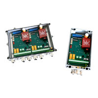
Magtrol LMU 212 User Manual (50 pages)
Load Monitoring Units
Brand:
Magtrol
| Category:
Measuring Instruments
| Size: 4 MB
Table of Contents
Table of Contents
4
Preface
6
Purpose of this Manual
6
Who Should Use this Manual
6
Installation / Configuration
6
Introduction
8
General Information
8
Data Sheet
9
Installation / Configuration
14
General Information
14
Installation of the LMU 212 and LMU 217 Load Monitoring Units
14
Fig. 2-1 Installation of the LMU 212 Load Monitoring Unit
15
Fig. 2-2 Installation of the LMU 217 Load Monitoring Unit
16
Connection of the LMU 212 and LMU 217 Load Monitoring Units
17
Fig. 2-3 Stuffing Gland (Overall and Exploded View)
17
Configuration of the Load Monitoring Unit
18
Adaptation of the Monitor to the Available Supply Unit
18
Fig. 2-4 Load Monitoring Unit Board with Location of the Selection Elements
18
Fig. 2-5 Jumper and Switch Configuration
19
Selection of the Type of Wiring to the Strain Gauge
20
Fig. 2-6 LMU Grounding When Using a 230, 115 or 48 VAC Supply
20
Designation of the Voltage and Current Inputs/Outputs
21
Configuration of the Detection Chains
21
Fig. 2-7 Wiring Types
21
Fig. 2-8 Location of the SWA Micro-Switches
22
Fig. 2-9 Examples of Switching Delays
24
Fig. 2-10 Potentiometer Location on the Load Monitoring Unit Board
25
Selection of the Pass Band
26
Selection of the Sensitivity Range
26
Fig. 2-11 Location of the SWB Micro-Switches on the Load Monitoring Unit Board
26
Selection of the Application
27
Fig. 2-12 Location of the SWC Micro-Switches on the Load Monitoring Unit Board
27
Division of the Transducer Signal or the Input Voltage U
28
By Two
28
Use Without Transducer
29
Fig. 2-13 Location of the Transducer Presence Simulation Jumpers
29
Calibration
30
Electrical Calibration (Standard)
30
Zero Adjustment on the Voltage Output
30
Fig. 3-1 Location of the Potentiometers on the Load Monitoring Unit Board
30
Zero Adjustment on the Current Output
31
Sensitivity Adjustment on the Voltage Output
31
Sensitivity Adjustment on the Current Output
31
Adjustment of the Detection Thresholds
32
Fig. 3-2 Location of the Micro-Switches SWC3 and SWC4 on the Load Monitoring Unit Board
32
Fig. 3-3 Location of the Relays REL1 and REL2 on the Load Monitoring Unit Board
33
Quick Calibration
34
Operations Preceding a Quick Calibration
34
Calibration Procedure
34
Calibration of the Built-In Test Equipment (B.I.T.E.)
35
Applications
36
Using One or Several Load Monitoring Units
36
Using One Single Load Monitoring Unit LMU 212
36
Fig. 4-1 Using One Single Load Monitoring Unit LMU 212
36
Using One Single Load Monitoring Unit LMU 217
37
Using Three Load Monitoring Units LMU 212
38
Using Transducers in Parallel
39
Operational Check of the Measuring Chain ("OK")
39
Checking the Transducer Signal Transmission to the Load Monitoring Unit
39
Fig. 4-4 Using One Single Load Monitoring Unit LMU 212
39
OK" Philosophy
40
Permanent Supply Check
40
Fig. 4-5 Permanent Supply Check LED
40
Using B.I.T.E. Signal
41
Fig. 4-6 B.I.T.E. Control Input Terminals
42
Repair
43
Trouble-Shooting
43
Configuration and Calibration Report
44
Lmu 212
45
Lmu 217
46
Appendix B : Ce Conformity Declaration
48
Magtrol Limited Warranty
49
Claims
49
Advertisement
Advertisement
Related Products
Magtrol LMU 217
Magtrol 1 PB 2.7-8
Magtrol 1 PB 2.7-8K
Magtrol 2 PB 2.7-8
Magtrol 2 PB 2.7-8K
Magtrol 2 WB 2.7-8K
Magtrol 3 WB 2.7-8K
Magtrol 4 PB 2.7-8
Magtrol 4 PB 2.7-8K
Magtrol 4 WB 2.7-8K
Magtrol Categories
Measuring Instruments
Controller
Power Supply
Transducer
Monitor
More Magtrol Manuals
Login
Sign In
OR
Sign in with Facebook
Sign in with Google
Upload manual
Upload from disk
Upload from URL