Sign In
Upload
Manuals
Brands
Magtrol Manuals
Measuring Instruments
HD Series
Magtrol HD Series Manuals
Manuals and User Guides for Magtrol HD Series. We have
1
Magtrol HD Series manual available for free PDF download: User Manual
Magtrol HD Series User Manual (76 pages)
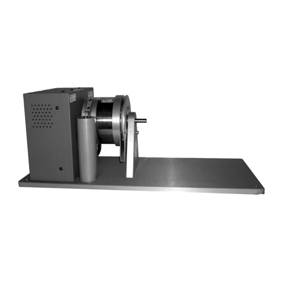
Hysteresis Dynamometers
Brand:
Magtrol
| Category:
Measuring Instruments
| Size: 5 MB
Table of Contents
Safety Precautions
4
Revisions to this Manual
5
Table of Contents
7
Table of Figures
9
Preface
10
Purpose of this MANUAL
10
Who Should USE this MANUAL
10
MANUAL Organization
10
Inputs/Outputs
10
Operating Principles
10
Conventions USED in this MANUAL
11
Introduction
12
Unpacking Your Hysteresis Dynamometer
12
FEATURES of the Hysteresis Dynamometer
13
Hd SERIES
13
Ed Series
13
DATA Sheet
14
Inputs/Outputs
27
Rear Panel
27
REAR PANEL INPUTS and Outputs
27
Figure 2-1 Rear Panel
27
Figure 2-2 Dynamometer Brake Input
27
Figure 2-3 Dynamometer Connector
27
Figure 2-4 Calibration Potentiometers
28
Figure 2-5 Speed Encoder Switch
28
Figure 2-6 Blower Input
28
Figure 2-7 Compressed Air Input
28
Installation/Configuration
29
Removal of the Load CELL Shipping/Restraining Bolt
29
Hd-100, -400 and -500 SERIES
29
Figure 3-1 HD 100-500 Series Shipping/Restraining Bolt Location
29
Hd-700 SERIES
30
Hd-800 SERIES
30
Figure 3-2 HD-700 Series Shipping/Restraining Bolt Location
30
Figure 3-3 ED-715 Shipping/Restraining Bolt Location
30
Earth Ground
31
Figure 3-4 HD 100-500 Series Top View
31
Figure 3-5 HD-800 Series Top View
31
SYSTEM Configurations
32
Manual Test Systems
32
Figure 3-6 Dynamometer with 6200 Controller
32
PC-Based TEST SYSTEMS
33
Figure 3-7 Dynamometer with DSP7001 Controller and M-TEST Software
33
Figure 3-8 Dynamometer with 6510E Power Analyzer, DSP7001 Controller and M-TEST Software
33
AIR Cooling
34
Installation/Configuration
34
Figure 3-9 Air Flow Sensor Schematic
34
Figure 3-10 Dynamometer with Blower Connection
35
Figure 3-11 Dynamometer with Compressed Air Connection
35
Testing
36
Testing Considerations
36
Safety
36
Accuracy
36
Power Dissipation
37
Figure 4-1 Power Absorption Curve Parameters
38
Figure 4-2 HD 106 Power Absorption Curve
39
Figure 4-3 HD 100 Power Absorption Curve
39
Figure 4-4 HD 400 Power Absorption Curve
40
Figure 4-5 HD 500 Power Absorption Curve
40
Figure 4-6 HD 510 Power Absorption Curve
41
Figure 4-7 HD 505 Power Absorption Curve
41
Figure 4-8 HD 515 Power Absorption Curve
42
Figure 4-9 HD 700 Power Absorption Curve
42
Figure 4-10 HD 710 Power Absorption Curve
43
Figure 4-11 HD 705 Power Absorption Curve
43
Figure 4-12 HD 715 Power Absorption Curve
44
Figure 4-13 HD 800 Power Absorption Curve
44
Figure 4-14 HD 810 Power Absorption Curve
45
Figure 4-15 HD 805 Power Absorption Curve
45
Figure 4-16 HD 815 Power Absorption Curve
46
Figure 4-17 HD 825 Power Absorption Curve
46
Figure 4-18 ED 715 Power Absorption Curve
47
Figure 4-19 ED 815 Power Absorption Curve
47
Figure 4-20 Dynamometer with Compressed Air Connection
48
Figure 4-21 Dynamometer with Blower Connection
48
Fixtures and Couplings
49
Windage
49
Figure 4-22 Examples of Possible Shaft Misalignment
49
Friction
50
Vibration
50
Cogging
51
Eddy Currents
51
Figure 4-23 Hysteresis Brake Cross-Section
51
Temperature Rise
52
Operating Principles
53
Speed
53
Torque
53
Figure 5-1 Mechanical Layout of a Load Cell
53
Torque Signal Amplification
54
DECIMAL Point Control
54
Damper Cylinder
55
Brake Control Power
55
Hd-800/815 and ED-815
55
Calibration
56
INITIAL Calibration
56
Calibration Beams and Weights
56
Figure 6-1 Calibration Label
56
Calibration Preparation
57
Calibration Procedure
57
Figure 6-2 Calibration Setup
57
Figure 6-3 Calibration Potentiometers
58
Figure 6-4 Calibration Calculation
58
Calibration Frequency
59
Optional Features
60
SPEED Encoder
60
Figure 7-1 Speed Encoder Schematic
60
Troubleshooting
61
Torque Readout Problems
61
NEW Dynamometer
61
Zero Balance
61
FULL SCALE Torque
62
Mechanical (Rotational) Alignment
64
Figure 8-1 Damper Connection
64
SPEED Readout Problems
65
Appendix A: Calibration Record
66
Appendix B: Schematics
67
Torque Amplification Board
67
SPEED Sensor Board
68
Load CELL Schematic
69
Hd-800-815 Brake Control SUPPLY
70
Hd-825 Brake Control SUPPLY
71
Index
72
Service Information
74
Returning Magtrol Equipment for REPAIR And/Or Calibration
74
Returning Equipment to Magtrol, INC. (UNITED STATES)
74
Returning Equipment to Magtrol SA (Switzerland)
74
Advertisement
Advertisement
Related Products
Magtrol HD-106-1
Magtrol HD-400-1
Magtrol HD-500-1
Magtrol HD-600-1
Magtrol HD-400
Magtrol HD-705
Magtrol HD-715
Magtrol HD-810
Magtrol HD-825
Magtrol HD-510
Magtrol Categories
Measuring Instruments
Controller
Power Supply
Monitor
Transducer
More Magtrol Manuals
Login
Sign In
OR
Sign in with Facebook
Sign in with Google
Upload manual
Upload from disk
Upload from URL