Sign In
Upload
Manuals
Brands
M&C Manuals
Measuring Instruments
GenTwo Multigas V2.4
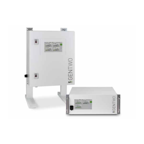
M&C GenTwo Multigas V2.4 Manuals
Manuals and User Guides for M&C GenTwo Multigas V2.4. We have
1
M&C GenTwo Multigas V2.4 manual available for free PDF download: Instruction Manual
M&C GenTwo Multigas V2.4 Instruction Manual (128 pages)
Brand:
M&C
| Category:
Measuring Instruments
| Size: 3 MB
Table of Contents
Table of Contents
3
Available Gases and Measuring Ranges: O 2 S and TCD Sensors
3
About this Instruction Manual
6
Important Safety Information
7
Intended Use
7
Personal Safety
7
Warning Signs and Definitions
7
Safety Instructions
9
Working on Electrical and Electronic Devices
10
Not Certified in Hazardous Areas
10
Introduction
11
Sensor Overview
12
Product Overview
12
Rack-Housing: Warning Symbols and Product Label
14
Fig. 1: Warning Symbols and Product Label on the Back
14
Receiving the Analyzer
14
Wall-Mount Housing: Warning Symbols and Product Label
15
Fig. 2: Product Label on the Side of the Wall-Mount Housing
15
Fig. 3: Warning Symbol at the Bottom of the Wall-Mount Housing
15
Fig. 4: Warning Symbols Inside Wall-Mount Housing
16
Fig. 5: Warning Symbol Close to the Relay Connections (Cover Removed)
16
Measuring Principles
17
Paramagnetic Oxygen Sensor (PMA2)
17
Technical Data Genx Sensor PMA2
17
Fig. 6: Electrochemical Oxygen Sensor with Flow Chamber
19
Electrochemical Oxygen Sensor
19
Technical Data of the Electrochemical Oxygen Sensor
19
Technical Data of the Electrochemical Hydrogen Sulfide Sensor
20
Thermal Conductivity Detector (TCD)
21
Technical Data TCD
21
Fig. 7: Thermal Conductivity Detector
21
NDIR/NDUV/UVRAS Photometers (Ultra.sens®, Infra.sens®)
22
Fig. 8: NDIR Module
23
Technical Data NDIR/NDUV/UVRAS Photometers
24
Fig. 9: NDUV Module
24
Available Gases and Measuring Ranges: NDIR Photometers
25
Available Gases and Measuring Ranges: UVRAS Photometers
26
Available Gases and Measuring Ranges: NDUV Photometers
26
Technical Data Basic Instrument
27
Dimensions 19"-Rack Housing
28
Fig. 10: 19"-Rack Housing Front View
28
Fig. 11: 19"-Rack Housing Side View (Long Housing)
29
Fig. 12: 19"-Rack Housing Side View (Short Housing)
29
Dimensions Wall-Mount Housing
30
Fig. 13: Wall-Mount Housing, Front and Side-View
30
Connections 19"-Rack and Wall-Mount Device
31
Fig. 14: Back View of 19"-Rack Housing with Connections (Max. Equipped)
31
Fig. 15: Bottom-View of Wall-Mount Device with Connections
31
Fig. 18: Wall-Mount Housing: USB Port for USB Stick
32
Fig. 17: Signal Connections Inside Wall-Mount Device (Max. Equipped)
32
Fig. 16: Power Supply Connections Inside Wall-Mount Device (W/O Protective Covers)
32
Electrical Interfaces: 19"-Rack Housing
33
Fig. 19: Electrical Interfaces: 19"-Rack Housing
33
Electrical Interfaces: Wall-Mount Housing
34
Fig. 20: Electrical Interfaces: Wall-Mount Housing
34
System Functions
35
Status Alarm
35
Accuracy of Ma Readings
35
Fig. 22: Second Part of the Startup Screen with Channel 3 to 6
36
Graphical User Interface (GUI)
36
Using the Analyzer
36
Fig. 21: Startup Screen of the 6-Channel Configuration
36
How to Use the Touch Screen
37
Menu Structure
38
Fig. 23: Menu Structure Overview M2/S2
38
System Status Line
39
Fig. 24: System Status Line
39
Main Menu Bar
40
Main Display Area
40
Fig. 25: Menu Bar with the Menu Items M1 to M6
40
Fig. 26: Main Display Area M2/S2
40
Fig. 27: Available Languages/Flags
41
Fig. 28: M1/S1 - M&C Contact Information
41
M1/S1 and M1/S2 - M&C Contact and GUI Version Number
41
Language Selection
41
Fig. 29: Swipe to Navigate through the Sections
42
Fig. 30: M1/S2 - Analyzer Configuration
42
Fig. 31: Detailed Information about the GUI Software Version
42
M1/S4 - Operating Hours Counter
43
M2/S1, M2/S2 - Measured Values, Operational Parameters and Limits
43
Fig. 32: Navigate Back to the M1/S1 Section
43
Fig. 33: M1/S4 - Operating Hours Counter (OHC)
43
Fig. 34: M2/S1 - Start Screen of the Home Button
44
Fig. 35: M2/S2 - Detailed View of the Measuring Parameters
44
Fig. 36: Navigate Back to the Start Screen
44
Fig. 38: M2/S2 - Using the Zoom Button
45
Fig. 37: M2/S2 - Detailed View During Warm-Up Period
45
M2/S3 - Event List
46
Fig. 39: Zoomed and Highlighted Area
46
M3/S1 - Data Logger/History Archive
47
Fig. 40: M2/S3 - Event List
47
Fig. 41: M3/S1 Data Logger Screen
47
Fig. 42: M3/S1 - Recorded Data Selection Screen
48
M4/S1 - Measuring Range Selection, Sensor Evaluation, Lim Settings
49
Fig. 43: Calibration Symbols to Highlight Calibration Procedures
49
Fig. 44: M4/S1 Edit Buttons for Measuring Range and Operational Parameter Settings
49
Fig. 45: Highlighted Scroll Bar to Select Measuring Range
50
Fig. 46: Sensor Evaluation List
51
Fig. 47: Highlighted Scroll Bars to Set Operational Parameter Lim1
52
Fig. 48: Highlighted Scroll Bar to Set Operational Parameter Lim2
52
M4/S2 - Settings Menu/ Parameters
53
Fig. 49: M4/S2 Screen with "Restart" Button
53
Fig. 50: Channel Settings
54
Fig. 51: Basic Settings for Channel 1
55
Fig. 52: Keypad
55
Fig. 53: Channel-Specific Settings List
56
Fig. 54: System Settings
58
Fig. 55: Scroll Bar with "4=Updates" Displayed in the Gray Frame
59
Fig. 56: Buttons to Get Information and Install Hardware and Software Updates
59
Fig. 57: Screen to Confirm the Update of the Application Software
60
Fig. 58: M4/S2 Screen with "Factory Reset" Selected
60
Fig. 59: Select Factory Settings
61
Fig. 60: Database Settings
61
Fig. 61: IP Address Input Screen
62
Fig. 62: Date and Time Settings
63
Fig. 63: Supervisor Settings for Administrators
64
Fig. 64: PDF1 Update
64
Fig. 65: Scroll Bar with "B=Diagnosis" Displayed in the Gray Frame
65
Fig. 66: Schematic for Diagnosis
65
Fig. 67: IO1 Component: DO1 to 4, Relay Outputs R1, R2 and Ma Output
66
Fig. 68: Display of the Highlighted IOAC-0 Components
66
M5/S1 and M5/S2 Calibration Menu
67
Fig. 69: Service Settings
67
Fig. 70: Gas Calibration Screen
67
M6/S1 Help Button
68
Fig. 71: Adjust Pressure Gauges and Flow Sensor
68
Mounting and Installation
69
General
69
Wall-Mount Housing: Electrical Connection
70
Fig. 72: Power Supply Connections Inside Wall-Mount Housing
71
Starting-Up and Operating the Analyzer
72
Preparations for Start-Up
72
Start-Up and Operation
72
Fig. 73: Warm-Up Phase in M2/S1 and Warm-Up Info on M2/S2
73
Fig. 74: Analyzer Is Ready to Operate
73
Confirm System Messages
74
Special Calibration Requirements for the TCD
75
M5/S1 Manual Calibration (Manucal)
75
General
75
Calibration
75
Fig. 75: Manual Calibration (Manucal)
76
Fig. 76: Setting the Channel-Specific Calibration Parameters
77
Fig. 77: Manual Calibration with Span Gas
77
Fig. 78: First Step of the Manual Calibration Procedure
78
Fig. 79: Second Step of the Manual Calibration Procedure
78
Fig. 80: Third Step of the Manual Calibration Procedure
79
Fig. 81: End of the Manual Calibration Procedure
79
Fig. 82: Data Logger Screen with Green Calibration Symbols
80
Fig. 83: a Terminated Manual Calibration Procedure
80
Fig. 84: Manual Calibration Error
81
Fig. 85: Datalogger Screen with Red Calibration Symbol
81
Automatic Calibration (Autocal)
82
Fig. 86: Screen Showing Details about a Single Calibration Procedure
82
Fig. 87: Activating Autocal and Entering Parameters
83
Fig. 88: Diagnostic Diagram: Opening the Output Card "IOAC 0" of Channel K2
84
Autocal for External Mounting of the Solenoid Valves
85
Fig. 89: Diagnostic Diagram: Opened Output Card for Channel K2
85
Fig. 90: Autocal Extern. Valves: Zero and Span Gas Via Gas Cylinder
85
Autozero Module (AZF)
86
Fig. 91: Autocal Ext. Valves: Zero Gas Via Filter and Pump, Span Gas Via Gas Cylinder
86
Fig. 92: Autozero Module (AZF)
86
Fig. 93: Autozero Basic Module with Options
87
Fig. 94: Autozero Basic Module with 3/2 Way Valve Y8 (Optionally)
87
Automatic Zero Gas Calibration with Autozero Module
88
Fig. 96: Autocal-Start Without Setting an Autocal Interval
89
Autocal or Autozero Start Without Cycle Setting
89
Fig. 95: Autozero: Activate Autocal Procedure and Select Zero Gas
89
Setting the Ma Behaviour During Calibration
90
Fig. 97: Autocal Start Without Setting the Interval: Channel Selection
90
Adjust Pressure Gauges and Flow Sensor
91
Fig. 98: Ma Setting: Page M4/S2, 3=Calibration/Adjustment
91
Fig. 99: Adjust Pressure Gauges and Flow Sensor
91
Cross-Sensitivity of Coexisting Gases
92
Cross-Sensitivity of Oxygen Sensor (PMA)
92
Fig. 100: Formula to Calculate the Effects of Coexisting Gases
93
Cross-Sensitivity of NDIR/NDUV Photometer
96
Cross-Sensitivity of Thermal Conductivity Detector (TCD)
96
Cross-Sensitivity of Electrochemical Oxygen Sensor
96
Service and Maintenance
97
Cleaning and Decontamination
98
Recommended Maintenance Work
98
Options and Spare Parts List
99
Risk Assessment
102
Fig. 101: Overview Risk Assessment
103
Appendix
105
Trouble Shooting
105
AK Protocol
105
Modbus Protocol
109
Warranty
117
Declaration of Conformity
117
Certificates
117
Additional Information
117
Liability and Disclaimer
118
Storage
118
Shipping and Handling
119
Proper Disposal of the Device
119
About Us
120
M&C's Group of Companies
120
The Quality-Oriented M&C Catalog
121
Technical Consulting Services
122
Ideas, Suggestions and Feedback
122
Table of Illustrations
123
Advertisement
Advertisement
Related Products
M&C V3/2-H
M&C V3/2-H/PE
M&C V3/2-H/EA
M&C 01A1000
M&C 01A2000
M&C 02S1800
M&C 02S1960
M&C 02S1965
M&C 02S1970
M&C 02S1980
M&C Categories
Measuring Instruments
Water Pump
Accessories
Laboratory Equipment
Industrial Equipment
More M&C Manuals
Login
Sign In
OR
Sign in with Facebook
Sign in with Google
Upload manual
Upload from disk
Upload from URL