Sign In
Upload
Manuals
Brands
LSIS Manuals
Controller
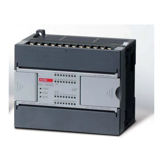
XEC-DN32H/DC
LSIS XEC-DN32H/DC Manuals
Manuals and User Guides for LSIS XEC-DN32H/DC. We have
1
LSIS XEC-DN32H/DC manual available for free PDF download: User Manual
LSIS XEC-DN32H/DC User Manual (236 pages)
Brand:
LSIS
| Category:
Controller
| Size: 6 MB
Table of Contents
Table of Contents
12
Chapter 1 Introduction
18
Guide to Use this Manual
18
Features
19
Terminology
21
Chapter 2 System Configuration
24
XGB System Configuration
24
Product List
25
Classification and Type of Product Name
27
Classification and Type of Main Unit
27
Classification and Type of Expansion Module
28
Classification and Type of Special Module
29
Classification and Type of Communication Module
30
Classification and Type of Option Module
30
System Configuration
31
Cnet I/F System
31
Ethernet System
34
Chapter 3 General Specifications
36
General Specifications
36
Chapter 4 CPU Specifications
38
Performance Specifications
38
Names of Part and Function
40
Power Supply Specifications
41
Calculation Example of Consumption Current/Voltage
43
Battery
45
Battery Specification
45
Notice in Using
45
Life of Battery
45
How to Change the Battery
46
Chapter 5 Program Configuration and Operation Method
48
Program Instruction
48
Program Execution Methods
48
Operation Processing During Momentary Power Failure
49
Scan Time
50
Scan Watchdog Timer
51
Program Execution
52
Configuration of Program
52
Program Execution Methods
52
Interrupt
54
Operation Mode
66
RUN Mode
66
STOP Mode
67
DEBUG Mode
67
Change Operation Mode
71
Memory
72
Program Memory
72
Data Memory
73
Data Retain Area Setting
73
Data Memory Map
75
Chapter 6 CPU Functions
76
Type Setting
76
Parameter Setting
77
Basic Parameter Setting
77
I/O Parameter Setting
78
Self-Diagnosis Function
79
Saving of Error Log
79
Troubleshooting
79
Remote Functions
81
Forced Input/Output on and off Function
82
Force I/O Setup
82
Direct Input/Output Operation
84
Diagnosis of External Device
85
Allocation of Input/Output Number
86
Online Editing
88
Reading Input/Output Information
91
Monitoring
92
RTC Function
97
How to Use
97
Chapter 7 Input/Output Specifications
100
Introduction
100
Digital Input Specifications of Main Unit
106
XEC-DR32H / XEC-DN32H Input Unit (Source/Sink Type)
106
XEC-DR64H / XEC-DN64H Input Unit (Source/Sink Type)
107
Digital Output Specification of Main Unit
108
XEC-DR32H Output Unit
108
XEC-DR64H Output Unit
109
XEC-DN32H Output Unit (Sink Type)
110
XEC-DP32H Output Unit (Source Type)
111
XEC-DN64H Output Unit (Sink Type)
112
XEC-DP64H Output Unit (Source Type)
113
Digital Input Module Specification
114
Point DC24V Input Module (Source/Sink Type)
114
Point DC24V Input Module (Sink/Source Type)
115
Point DC24V Input Module (Source/Sink Type)
116
Digital Output Module Specifications
117
Point Relay Output Module
117
Point Transistor Output Module (Sink Type)
119
Point Transistor Output Module (Sink Type)
120
Point Transistor Output Module (Source Type)
122
Point Transistor Output Module (Source Type)
124
Combined Module Digital Input Specification
125
Point DC24V Input Part (Source/Sink Type)
125
Point DC24V Input (Source/Sink Type)
126
Combined Module Digital Output Specification
127
Point Relay Output Part
127
IO Wiring by Using Smart Link Board
129
Smart Link Board
129
Chapter 8 Built-In High-Speed Counter Function
134
High-Speed Counter Specifications
134
Designation of Parts
135
Counter Function
137
Installation and Wiring
154
Precaution for Wiring
154
Example of Wiring
154
Internal Memory
155
Special Area for High-Speed Counter
155
Error Code
160
Examples: Using High-Speed Counter
161
Chapter 9 Installation and Wiring
166
Safety Instruction
166
Fail Safe Circuit
168
PLC Heat Calculation
171
Attachment/Detachment of Modules
173
Caution in Handling
173
Wire
179
Power Wiring
179
I/O Device Wiring
182
Grounding Wiring
182
Specifications of Wiring Cable
183
Chapter 10 Maintenance
184
Maintenance and Inspection
184
Daily Inspection
184
Periodic Inspection
185
Chapter 11 Troubleshooting
186
Basic Procedure of Troubleshooting
186
Troubleshooting
186
Troubleshooting Flowchart Used with When the ERR(Error) LED Is Flickering
188
Troubleshooting Flowchart Used with When the I/O Part Doesn't Operate Normally
190
Troubleshooting Questionnaire
192
Troubleshooting Examples
193
Input Circuit Troubles and Corrective Actions
193
Output Circuit and Corrective Actions
194
Error Code List
196
Appendix 1 Flag List
198
Appendix 1.1 Special Relay (F) List
198
Appendix 1.2 Communication Relay (L) List
202
Appendix 1.3 Network Register (N) List
205
Appendix 2 Dimension
206
Advertisement
Advertisement
Related Products
LSIS XEC-DN30SU
LSIS XEC-DN32H
LSIS XEC-DN30E
LSIS XEC-DN32U
LSIS XEC-DN32UP
LSIS XEC-DN32UA
LSIS XEC-DN40SU
LSIS XEC-DN60SU
LSIS XEC-DN64H
LSIS XEC-DN14E
LSIS Categories
Controller
Inverter
Control Unit
DC Drives
Relays
More LSIS Manuals
Login
Sign In
OR
Sign in with Facebook
Sign in with Google
Upload manual
Upload from disk
Upload from URL