Sign In
Upload
Manuals
Brands
LS ELECTRIC Manuals
Servo Drives
Xmotion L7P Series
LS ELECTRIC Xmotion L7P Series Manuals
Manuals and User Guides for LS ELECTRIC Xmotion L7P Series. We have
1
LS ELECTRIC Xmotion L7P Series manual available for free PDF download: User Manual
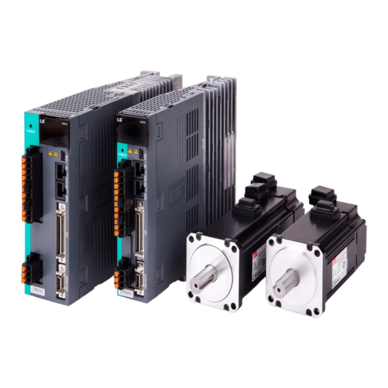
LS ELECTRIC Xmotion L7P Series User Manual (531 pages)
Brand:
LS ELECTRIC
| Category:
Servo Drives
| Size: 14 MB
Table of Contents
Table of Contents
9
Product Configuration
15
Product Verification
15
Product Specifications
16
Part Names
18
Servo Drive Parts
18
Servo Motor Parts
29
System Configuration Example
30
Product Feature
31
Servo Motor
31
Product Feature
50
Outline Drawing
61
Servo Drive
74
Product Features
74
Outline Drawing
78
Options and Peripheral Devices
84
Wiring and Connection
105
Installation of Servo Motor
105
Operating Environment
105
Preventing Impact
105
Motor Connection
106
The Load Device Connection
107
Cable Installation
107
Installation of the Servo Drive
108
Installation and Usage Environment
108
Installation in the Control Panel
109
Internal Block Diagram of Drive
111
Block Diagram of Drive (100W~400W/200[V])
111
Block Diagram of Drive (800W~3.5Kw/200[V])
112
Block Diagram of Drive (5Kw~7.5Kw/200[V])
113
Block Diagram of Drive (15Kw / 200[V])
114
Block Diagram of Drive (1Kw~3.5Kw/400[V])
115
Block Diagram of Drive (5Kw~7.5Kw/400[V])
116
Block Diagram of Drive (15Kw/400[V])
117
Power Supply Wiring
118
Power Supply Sequence
122
Power Circuit Electrical Components
123
Regenerative Resistance Option Spec
127
Wiring for Input/Output Signals
129
Names and Functions of Digital Input/Output Signals
130
Names and Functions of Analog Input/Output Signals
134
Pulse String Input Signalnames and Functions
135
Names and Functions of Encoder Output Signals
135
Examples of Connecting Input/Output Signals
136
Pulse String Input Signal
140
Connection Diagram of I/O Signal
141
Encoder Signal (ENCODER Connector) Wiring
142
Option Cable Connection Example
142
Linear Scale and Third Party Encoder Connection Example
147
L7P Indexer Overview
149
Control Method
149
Indexing Position Operation
149
Coordinate System Setting
153
Index Structure
155
Pulse Input Position Operation
156
Speed Operation
159
Torque Operation
163
Indexing Position Operation
167
Index Concept
167
Index Type
174
Absolute / Relative Move
174
Registration Absolute / Relative Move
175
Blending Absolute / Relative Move
176
Rotary Absolute / Relative Move
177
Rotary Shortest Move
178
Rotary Positive / Negative Move
179
Functions of INDEX Input Signals
180
Functions of INDEX Output Signals
185
Analog Velocity Override
188
Pulse Input Position Operation
191
Function Setting of Pulse Input Logic
192
Function Setting of Pulse Input Filter
193
Features of PCLEAR
194
Features of INHIBIT
195
Speed Operation
197
Function Setting of Speed Command Switch Selection
197
Analog Velocity Command
198
Multi-Speed Command
200
Torque Operation
201
Analog Torque Command Scale
201
Speed Setting for Torque Operation
202
Speed Limit Function
202
Operation Mode Change
203
High Speed Homing
205
Homing Method
206
Drive Application Function
219
Drive Front Panel
219
7-Segment for Indicating Servo Status
219
Configuration of Drive Node Address
222
Terminating Resistor Setting
223
Input/Output Signals Setting
224
Allocation of Digital Input Signals
224
Assignment of Digital Output Signals
228
Use of User I/O
231
Electric Gear Setup
236
Electric Gear
236
Example of Electric Gear Setup
238
Calculation of Speed and Acceleration/Deceleration When Using Electronic Gear11-21
239
Settings Related to Speed Control
241
Smooth Acceleration and Deceleration
241
Servo-Lock Function
242
Signals Related to Speed Control
242
Settings Related to Position Control
243
Position Command Filter
243
Signals Related to Position Control
245
Positive/Negative Limit Settings
246
Setting the Brake Output Signal Function
247
Torque Limit Function
249
Gain Switching Function
252
Gain Group Switching
252
P/PI Control Switching
254
Motor Overload Protection
256
Protection by Motor Thermal Time Constant
257
Dynamic Brake
258
Regeneration Brake Resistor Configuration
260
Use of Internal Regenerative Resistor
261
Use of External Regenerative Resistor
263
Other Considerations
265
Touch Probe Function
266
Encoder Signal Output
269
Absrq
271
Tuning
273
Off-Line Auto Gain Tuning
274
On-Line Auto Gain Tuning
276
Manual Gain Tuning
279
Gain Tuning Sequence
279
Vibration Control
282
Notch Filter
282
Adaptive Filter
283
Vibration Control (Damping) Filter
284
Analog Monitor
285
Procedure Function
289
Manual JOG Operation
290
Programmed Jog Operation
291
Automatic Gain Tuning
293
Index Pulse Search
293
Absolute Encoder Reset
294
Instantaneous Maximum Torque Initialization
295
Phase Current Offset Tuning
296
Software Reset
296
Commutation
296
Object Dictionary
297
Data Type
298
General Objects
299
Manufacturer Specific Objects
303
Index Objects
375
Cia402 Objects
382
Maintenance and Inspection
399
Diagnosing and Troubleshooting Abnormalities
399
Precautions
399
What to Inspect
400
Replacing Parts
401
Servo Alarm
402
Servo Warning
407
How to Replace the Encoder Battery
410
Servo Overload Characteristic Curve
411
Servo Overload Motor Type and ID (Continued on Next Page)
423
Communication Protocol
427
Overview and Communication Spec
427
Overview
427
Communication Specification and Cable Connection Diagram
428
Communication Protocol Basic Structure
429
Sending and Receiving Packet Structure
429
Protocol Command Code
431
L7P Indexer Servo Drive Communication Address Table
484
General Objects
484
System Configuration Parameters
485
Control Parameters
487
Input and Output Parameters
488
Velocity Operation Parameters
490
Miscellaneous Parameters
491
Advanced Control Parameters
492
Monitoring Parameters
493
Procedures and Alarm History
493
3Rd Party Motor Parameters
494
Cia402 Parameters
495
Index Related Parameters
497
Index00 ~Index63 Internal Variable Communication Address
500
Test Operation
501
Preparation for Operation
502
Indexing Position Operation
503
Pulse Input Position Operation
507
Speed Operation
510
Torque Operation
514
Example of Connection with Upper Level Device (Pulse Input Position)
517
Example of Connection with LSELECTRIC XGF-PO1/2/3A
518
Example of Connection with LSELECTRIC XGF-PO1/2/ 3H
520
Appendix
523
Firmware Update
523
Use of USB OTG
523
Use of Drive CM
524
Advertisement
Advertisement
Related Products
LS ELECTRIC L7NHFA010U
LS ELECTRIC L7NHA001U
LS ELECTRIC L7NHA075U
LS ELECTRIC L7NHB035U
LS ELECTRIC Xmotion L7SA004X
LS ELECTRIC Xmotion L7SA020X
LS ELECTRIC Xmotion L7SA075B
LS ELECTRIC Xmotion L7SB075B
LS ELECTRIC Xmotion L7CA001U
LS ELECTRIC Xmotion L7CA010U
LS ELECTRIC Categories
Controller
Control Unit
DC Drives
Servo Drives
Inverter
More LS ELECTRIC Manuals
Login
Sign In
OR
Sign in with Facebook
Sign in with Google
Upload manual
Upload from disk
Upload from URL