Sign In
Upload
Manuals
Brands
Lombardini Manuals
Engine
5LD825-3
Lombardini 5LD825-3 Manuals
Manuals and User Guides for Lombardini 5LD825-3. We have
1
Lombardini 5LD825-3 manual available for free PDF download: Workshop Manual
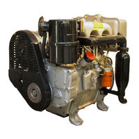
Lombardini 5LD825-3 Workshop Manual (63 pages)
Brand:
Lombardini
| Category:
Engine
| Size: 5.11 MB
Table of Contents
Index
2
Contents
3
Model Number and Engine Identification
6
Characteristics
7
Characteristic Power, Torque and Specific Consumption Curves
8
Maintenance
9
Recommended Oil Type
9
Capacities
9
Trouble Shooting
10
Possible Causes and Trobule Shooting
10
Overall Dimensions
11
Main Torque Specifications
13
Standard Bolt Torque Specifications
14
Use of Sealants
15
Disassembly and Reassembly
16
Oil-Bath Air Cleaner (Standard)
16
Oil-Bath Air Cleaner Components
16
Dry Air Cleaner
16
Exhaust Manifold
17
Intake Manifold
17
Fan Control Belt
17
Belt Tension Adjustment
17
Blower Assembly
18
Blower Assembly Components with 14A Alternator
18
Blower Assembly Components with 21A Alternator
18
Oil Cooler
19
Tank
19
Flywheel
19
Valve/Rocker Arm Clearance
20
Rocker Arm Assembly
20
Injector
20
Valves
21
Valve Spring
21
Valve Material
21
Valve Guides and Valve Guide Housings
21
Valve Guide Insertion
22
Dimensions and Clearance between Guides and Valves
22
Valve Seats and Housings
22
Valve Seat Grinding
22
Injector Projection
23
Pushrod Tube Spring
23
Head Tightening
23
Cylinder
24
Piston
24
Cylinder Roughness
24
Piston Availability
24
Checking that Piston Is an Original Part
25
Piston Weight
25
Piston Rings - End Gaps
25
Piston Rings - Clearance between Grooves
25
Piston Rings - Fitting Sequence
26
Piston - Refitting
26
Piston Clearance
26
Connecting Rod
27
Connecting Rod, Small End Bearing Pin
27
Connecting Rod Alignment
28
Connecting Rod Weight
28
Connecting Rod Big End Bearing
28
Crankshaft Pulley
29
Timing Cover
29
Camshaft Gear
29
Idler Gear and Support
30
Oil Pump Gear
30
Speed Governor Lubricating Tube
30
Timing Gear for 5LD825-2
31
Timing Gear for 5LD825-3, 5LD825-3/T, 5LD930-3, 5LD825-4 and 5LD930-4
31
Main Bearing Support, Flywheel Side
31
Crankshaft
31
Crankshaft Removal
32
Crankshaft Center Main Bearing Supports
32
Thrust Ring
32
Oil Sprayer
32
Crankshaft End Play
33
Crankshaft Lubrication Ducts
33
Crankshaft Journal Radius
33
Main Bearing Supports
34
Main Bearing Housings
34
Camshaft Removal
35
Camshaft Bearing and Journal Inside Diameter
35
Dimensions of Camshaft
35
Intake/Exhaust Cam Height
36
Camshaft Plugs
36
Camshaft Timing
36
Valve Timing Without Considering Timing Marks
37
Valve Timing Check
37
Hydraulic Pump P.t.o.
38
Hydraulic Pump 3Rd P.t.o.
38
Speed Governor
38
Ball-Type Speed Governor
38
Weight-Type Speed Governor for Generating Seats
39
Speed Governor Operation
39
Spring for Extra Fuel Supply at Starting
39
Speed Governor Spring Hook-Up
40
Speed Governor Springs with Rocker Yoke
40
Speed Governor Timing with Injection Pump
41
Turbocharger
41
Turbocharger Components
41
Lubrication System
42
Lubrication System Layout
42
Oil Pump
43
Oil Pressure Relief Valve
43
Oil Filter
43
Oil Pressure Check
44
Oil Pressure Curve at Idling Speed
44
Oil Pressure Curve at Full Speed
44
Fuel System
45
Fuel Feeding/Injection System
45
Fuel Filter
45
Fuel Feeding Pump
45
Fuel Feeding Pump Drive Rod Protrusion
46
Injection Pump
46
Injection Pump Components
46
Barrel and Plunger for 5LD825-2
47
Barrel and Plunger for 5LD825-3
47
Barrel and Plunger for 5LD930-3, 5LD825-3/T
47
Injection Pump Delivery Valve
47
Checking Barrel and Plunger for Internal Leakage
48
Checking Injection Pump Delivery Valve Sealing
48
Injection Pump Delivery Testing for 5LD825-2 - Pump Type
48
Test Data
48
Injection Pump Reassembly to the Engine - Pump Type Bosch PES
50
Static Injection Timing
50
Injection Timing Correction with Injection Pump Type
50
Static Injection Timing Correction
51
Static Injection Reference Marks on Crankcase and Flywheel
51
Injection Timing Reference Marks on the Pulley and the Gear Cover
51
Nozzle
52
Injection Setting
52
Electric System
53
Electrical Starting Layout Without Battery Charging Light
53
Electrical Starting Layout with Battery Charging Light
53
Alternator Battery Charging Curve
54
12 V, 21 a Alternator
54
Alternator Battery Changer Curve
54
Checking for Cable Continuity
55
Voltage Regulator
55
Checking Voltage Regulator for Proper Operation
55
Alternator Type Bosch G1, 14 V, 33 a
56
Bosch G1 Alternator Battery Charger Curve
56
Starting Motor
57
Characteristic Curves for Starting Motor Type
58
Key Switch
58
Settings
59
Idling Speed Setting in No-Load Conditions
59
Full Speed Setting in No-Load Conditions
59
Injection Pump Delivery Setting
59
Injection Pump Delivery Setting with Engine on the Torque Dynamometer
60
Required Settings
60
Stop Setting
60
Storage
61
Temporary Protection
61
Permanent Protection
61
How to Prepare the Engine for Operation
61
Special Equipment
62
Advertisement
Advertisement
Related Products
Lombardini 5LD825-4
Lombardini 5LD930-3
Lombardini 5LD825-2
Lombardini 5LD930=4
Lombardini 5LD825-3/T
Lombardini 5LD8252/L
Lombardini 5LD675-2
Lombardini 5LD673-3
Lombardini 5LD825-3/L
Lombardini 5LD825-4/L
Lombardini Categories
Engine
Air Conditioner
Controller
More Lombardini Manuals
Login
Sign In
OR
Sign in with Facebook
Sign in with Google
Upload manual
Upload from disk
Upload from URL