Sign In
Upload
Manuals
Brands
LiuGong Manuals
Front End Loaders
CLG835H
LiuGong CLG835H Front End Loader Manuals
Manuals and User Guides for LiuGong CLG835H Front End Loader. We have
2
LiuGong CLG835H Front End Loader manuals available for free PDF download: Service Manual, Operation And Maintenance Manual
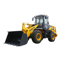
LiuGong CLG835H Service Manual (764 pages)
WHEEL LOADER
Brand:
LiuGong
| Category:
Front End Loaders
| Size: 14.05 MB
Table of Contents
Table of Contents
3
General Information
5
How to Use the Manual
7
Engine Identification
10
Cable Code Identification
12
Coating Materials
14
Weight Table
16
Unit Conversion Table
17
Standard Torque Table
18
Oils Use Specifications
21
Technical Specification of the Complete Machine
25
Power System
39
Basic Information
41
Safety
41
Overview-Components and Position
43
System Technical Parameters
47
Universal Tool, Tooling List
48
Structure Function Principle
49
Engine System
49
Overview
49
Diesel Engine
50
Intake and Exhaust System
62
Intake and Exhaust Assembly
62
Air Filter
65
Diesel Particle Filter System
67
DEF Pipeline Assembly
68
DEF Tank
70
DEF Pump
73
Cooling System
75
Overview
75
Radiator Group
80
Fan
82
Refilling and Replacement of Coolant
82
Fuel System
83
Fuel Tank Assembly
83
Fuel Lines
84
Power Train System
155
Basic Information
157
Safety
157
System Composition and Position
158
System Technical Parameters
158
System Schematic Diagram and Working Principle Description
159
Overview of Transmission Fluid
161
Maintenance and Replacement of Gearbox and Drive Axle Oil
162
Universal Tool, Tooling List
163
Special Tool, Tooling List
163
Structure Function Principle
164
Torque Converter - Gearbox System
164
Drive Axle System
170
Drive Shaft System
172
Tire&Rim System
173
Testing and Adjustment
177
Torque Converter - Gearbox System
178
Drive Axle System
178
Removal and Installation
179
Removal and Installation of Torque Converter-Gearbox System
179
Disassembly and Assembly of Torque Converter-Gearbox Assembly
191
Removal and Installation of Drive Shaft System
192
Removal and Installation of Front Axle Assembly
197
Removal and Installation of Rear Axle Assembly
200
Disassembly and Assembly of the Drive Axle
210
Fault Diagnosis and Troubleshooting Methods
211
Power Train System
214
Basic Information
215
Safety
215
System Composition and Position
216
System Technical Parameters
216
System Schematic Diagram and Working Principle Description
217
Overview of Transmission Fluid
219
Maintenance and Replacement of Gearbox and Drive Axle Oil
220
Universal Tool, Tooling List
221
Special Tool, Tooling List
221
Structure Function Principle
222
Torque Converter - Gearbox System
222
Drive Axle System
228
Drive Shaft System
230
Tire&Rim System
231
Testing and Adjustment
235
Torque Converter - Gearbox System
235
Drive Axle System
235
Removal and Installation
236
Removal and Installation of Torque Converter-Gearbox System
236
Disassembly and Assembly of Torque Converter-Gearbox Assembly
248
Removal and Installation of Drive Shaft System
249
Removal and Installation of Front Axle Assembly
254
Removal and Installation of Rear Axle Assembly
257
Disassembly and Assembly of the Drive Axle
267
Fault Diagnosis and Troubleshooting Methods
268
Testing and Adjustment
270
Power Train Test
270
Hydraulic System
273
Basic Information
277
Safety Precautions for Hydraulic System
277
Overviews of Hydraulic System
280
Technical Parameters of Hydraulic System
283
Hydraulic System Principle Schematic
283
Universal Tools and Tooling for Hydraulic Maintenance
284
Special Tools and Tooling for Hydraulic Maintenance
285
Structure Function Principle
290
Work Hydraulic System
290
Hydraulic Oil Tank
291
Plunger Pump
292
Boom Cylinder
294
Bucket Cylinder
294
Control Valve
295
Pilot Valve
307
Steering Hydraulic System
309
Steering Pump
312
Metering Pump
312
Priority Valve
314
Steering Cylinder
317
Brake System
318
Brake Pump
322
Brake Valve
326
Charge Valve
329
Accumulator Assembly
331
Brake Cylinder
334
Hydraulic Cooling System
336
Cooling Pump
340
Cooling Motor
340
Solenoid Directional Valve
341
Emergency Steering System
343
Pilot System of Electronic Control Third Linkage
345
Testing and Adjustment
347
Pressure Release of Hydraulic System
347
Pressure Test of Work Hydraulic System
350
Positions of Every Gauging Points of Working Hydraulic System
350
Description of Every Gauging Points of Working Hydraulic System
351
Inspection and Adjustment for Pressure of Working Hydraulic Pressure System
352
Pressure Inspection and Adjustment of Overload Valve of Bucket Tilting Large Chamber
356
Pressure Inspection and Adjustment of Overload Valve of Bucket Tilting Small Chamber
358
Pressure Inspection and Adjustment of Main Safety Valve of Control Valve
360
Inspection and Adjustment for Cut-Off Pressure of Working Pump
362
Adjustment for LS Relief Pressure of Control Valve
364
Pressure Inspection and Adjustment of the Pilot Oil Supply Valve
366
Boom Cylinder Test
368
Bucket Cylinder Test
369
Steering Hydraulic System Test
370
Measuring Point Position of Steering Hydraulic System
370
Description of Measuring Points of Steering Hydraulic System
371
Pressure Testing and Adjustment of Steering Hydraulic System
371
Steering Cylinder Test
373
Brake System Test
374
Layout of Pressure Measuring Points of Brake System
374
Test Method of Rear Axle Brake Pressure
375
Test Method of Front Axle Brake Pressure
377
Removal and Installation
378
Work Hydraulic System
378
Removal and Installation of Hydraulic Oil Tank Assembly
378
Removal and Installation of the Plunger Pump
382
Removal and Installation of Boom Cylinder
387
Disassembly and Assembly of Boom Cylinder
392
Removal and Installation of Bucket Cylinder
405
Disassembly and Assembly of Bucket Cylinder
409
Removal and Installation of Control Valve
422
Removal and Installation of Pilot Valve Assembly
431
Removal and Installation of Metering Pump
435
Air Conditioning System
507
Basic Information
509
Safety
509
Universal Tool, Tooling List
509
Special Tool, Tooling List
510
Structure Function Principle
510
Components and Position
510
System Technical Parameters
511
Description of Principle Diagram and Working Principle
512
Testing and Adjustment
515
Air Conditioning System Test
515
Removal and Installation
517
Introduction of Air Conditioner System Main Parts
517
Removal and Installation of A/C Components
518
Removal of Compressor
518
Removal and Installation of Evaporator Mounting Assembly
525
Replacement of A/C Control Panel
531
Inspection and Replacement of A/C Fuse
531
Removal and Replacement of Reservoir
532
Removal and Installation of Condenser
533
Removal and Installation of Pressure Switch
534
Fault Diagnosis and Judgment
535
Classification of Common Faults
535
Overhauling Method
535
Maintenance Method When Backlight of A/C Panel Is Not on and Button Does Not Work
535
Maintenance Method When no Air Comes out of Air Conditioner or Air Outlet Volume Is Obviously Smaller than the Normal Volume
536
Maintenance Method When Natural Air Comes out When Heating Is Switched on
542
System Maintenance
543
A/C System Regular Maintenance
543
Cleaning of Recirculating Air Strainer
543
Cleaning of Fresh Air Strainer
544
Driver's Cab System
551
Structure Function Principle
553
Engine Hood
553
Engine Hood Assembly
553
Opening and Closing of Engine Hood
555
Lifting Mechanism of Engine Hood Torsion Bar
557
Removal and Installation
560
Installation Requirements for Shock Cushion of Cab
560
Removal and Installation of Cab
560
Removal of Air Conditioning Components in Cab
560
Disassembly of Hydraulic Components in Cab
560
Disassembly of Power Components in Cab
566
Replacement and Installation for Lifting Rings of Head Cover
570
Removal of Shock Cushion
570
Lift
571
Removal of the Seat
571
Exploded View of Driver Seat
571
Removal of the Seat
573
Removal of Console
576
Removal of Decoration
580
Removal of the Rear Right Positioning Lock Trim Cover in the Cab
580
Removal of Left Decoration of Cab
581
Removal of Right Decoration of Cab
584
Removal of Decoration of Rear Plate
585
Removal of Decoration and Platform and Attachment
587
Top Decorations of Cab
588
Assemble the Glass of Cab
589
Installation of the Left Door Lock in Cab
591
Removal and Installation of Engine Hood
596
Removal and Installation of the Engine Hood Torque Mechanism
602
Structure
607
Structure Function Principle
609
Frame System
609
Articulated Hitch
610
Counterweight Assembly
611
Work Implement
612
The Parameters of Work Implement
612
Overview and Configuration Scheme of Work Implement System
612
Work Implement Limit System
614
Removal and Installation
615
Removal and Installation of Hinge Assembly
615
Removal and Installation of Counterweight Assembly
626
Removal and Installation of Work Implement System
628
Removal and Installation of Linkage
628
Removal and Installation of Bucket Lever
631
Removal and Installation of the Boom
634
Replacement of Work Implement Bushing
638
Removal and Installation of Accessory System
640
Removal and Installation of Quick Coupler Bucket and Quick Coupler Frame
647
Replacement of Bucket Movable Blade, Movable Tooth and Tip
655
Option Work Implement and Accessory System
656
Option of Work Implement System
656
Option of Accessory System
656
Electrical System
659
Basic Information
663
Instructions of Service Manual
663
Notes for Welding
663
The Introduction of Signs on the Electrical Schematic
665
Structure Function Principle
667
Power System
667
Electric Lock
669
Fuse
670
Disconnect Switch
673
Battery
674
Power Supply Relay
676
Starting Module
679
Start Contactor
682
Relay
682
Starting Motor
683
Alternator
684
Monitoring System
686
Circuit for Engine Water Temperature Indication
686
Circuit for Torque Converter Oil Temperature Indication
686
Circuit for Oil Pressure Alarm
688
Circuit for Transmission Oil Pressure Alarm
688
Circuit for Fuel Level Indication
689
Circuit for DEF Level Indication
691
Circuit for Vehicle Speed Indication
691
Service Brake Indication Circuit
691
Wiring Schematic Diagram of Braking
692
Circuit for Parking Brake Power Cut-Off
694
Circuit for Service Brake Clutch On/Off
697
Circuit for Air Filter Blockage Alarm
698
Circuit for Alternator Charging Indication
698
Circuit for Voltage Indication
700
Circuit of Preheat Indicator
701
Circuit for Seatbelt Indicator
702
Circuit for Lube System Failure Indicator
702
Circuit for Lube System Activated Indicator
703
Circuit for Steering System Failure Indicator
703
Circuit for Secondary Steering Indicator
704
Circuit of Ride Control Indicator
706
Circuit for Radiator Fan Reverse Indicator
709
Circuit for Engine Indicator
710
Circuit for Engine Diesel Particle Filter Indicator
710
Circuit for Latency Shut-Down Indicator
710
Instrument
711
Sound and Light Alarm System/Audible and Visual Alarm System/Acousto-Optic Alarm System
715
Circuit for Electric Horn
715
Circuit for Backup Alarm
717
Wiper and Washer System
718
Circuit Diagram for Wiper and Cleaning System
718
Wiper Motor
719
Washer Reservoir
720
Positioner and Kickout System
721
Principle for Auto Reset System
721
Lighting System
723
Circuit for Front Frame Illumination
723
Circuit for Cab Lighting
726
Circuit for Rear Frame Illumination
729
Shift Control System
731
Principle for Shift Control
732
Electronic Control Unit
735
Shift Selector
735
Audio System
737
Audio System Principle
737
Radio
738
Speaker
738
Antenna
738
Engine Electric Control Module
739
DEF Heater Pipe
739
Principle for Exhaust Disposal
740
Electronic Throttle Line
740
DEF Pump Supply Module Line
741
Radiator Fan Control Module
741
Control Strategy
741
Electrical Schematic Diagram
741
Electric Proportional Controller Module of the Third Linkage
742
Seat Heater
744
Backup Monitoring System
745
Display Screen
746
Power Cable
746
Distribution Diagram of Front Frame Harness Connector
747
Distribution Diagram of Work Light Harness Connector
749
The Distribution Diagram of Cab Harness Connector
751
Distribution Diagram of Rear Frame Harness Connector
753
Appendix
755
Schematic Diagram of Hydraulic System
757
Schematic Diagram of Brake System
758
A/C System Schematic Diagram
759
Electrical Schematic Diagram
760
Advertisement
LiuGong CLG835H Operation And Maintenance Manual (238 pages)
WHEEL LOADER
Brand:
LiuGong
| Category:
Front End Loaders
| Size: 13.18 MB
Table of Contents
Table of Contents
5
Preface
7
Safety Information
13
Safety Decals and Decal Locations
13
General Hazard Information
27
Crushing and Cutting Prevention
31
Burn Prevention
31
Fire & Explosion Prevention
32
Fire Extinguishers and First-Aid Kit
33
Electrical Storm Injury Prevention
34
Tire Explosion Prevention
34
Rops/Fops
35
Operator Station
35
Steering Frame Lock
35
Attachment Cautions
35
Cautions about Machine Operation
35
Cautions about Machine Maintenance
42
Sound and Vibration
44
Key Spare Parts to be Periodically Changed
45
Application and Specification
46
Applications
46
Main Specifications
47
Operation Manual
53
Before Operation
53
Operator Controls and Instrument Panels
54
Engine Starting
114
Operation Techniques
116
Transportation Information
125
Maintenance Manual
129
Maintenance Guidance
129
Run-In
131
Maintenance Interval Schedule
132
General Torque Specifications
136
Tire Inflation Information
137
Lubrication Specifications
138
Important Maintenance Procedures
140
Hydraulic Oil--Add
174
Hydraulic Oil--Replace
174
Serious Polluted Hydraulic Oil
176
Return Oil Filter Element
176
Hydraulic Oil Tank--Clean
179
Pilot Filter Element--Replace
180
Pre-Charge Pressure of Pilot Oil Supply Valve Accumulator
181
Accumulator of Pilot Oil Supply Valve--Charge
182
Note: ★ ★ ★ Indicates the First Service Interval
184
Boom Lift Kickout--Adjust
208
Bucket Cutting Edges--Check
209
Backup Alarm--Test
210
Seat Belt--Inspect
210
Window Washer Reservoir--Fill
210
Index
235
Advertisement
Related Products
LiuGong Categories
Front End Loaders
Automobile Accessories
More LiuGong Manuals
Login
Sign In
OR
Sign in with Facebook
Sign in with Google
Upload manual
Upload from disk
Upload from URL