Sign In
Upload
Manuals
Brands
Link Controls Manuals
Control Unit
CS 320
Link Controls CS 320 Manuals
Manuals and User Guides for Link Controls CS 320. We have
1
Link Controls CS 320 manual available for free PDF download: Assembly Instructions Manual
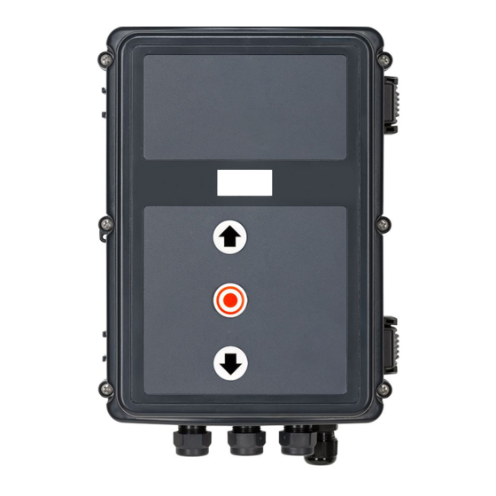
Link Controls CS 320 Assembly Instructions Manual (64 pages)
Brand:
Link Controls
| Category:
Control Unit
| Size: 5 MB
Table of Contents
Table of Contents
2
Contents
2
Information in this Document
3
General Safety Instructions
3
Product Overview
4
Product Description
4
Variants
4
Motherboard CS 320
5
Installation
6
Safety Instructions for Installation
6
Mains Connection
6
Internal Fuse Protection
7
Mains Voltage Selection
8
Supply to External Devices
8
(Only with 400 V / 3-Phase Connection)
8
Connection of Electronic Limit Position System Absolute Value Encoder (AWG)
9
Mechanical Limit Switch (MEC) Connection
9
Connection of Command Devices
12
Light Grid Connection
14
Connection of Closing Edge Protective
15
Connection Light Barrier 1
16
Terminal Assignment, Relay Outputs
17
Connection of Programmable Inputs
17
Safety Input Per en 12453
20
Radio Receiver, Pluggable
21
CS Radio
22
Digital 991
22
Connection of External Radio Receiver
23
Connection of Frequency Converter
23
Connection of LCD Monitor
24
Connection of MS BUS Components
24
Transmission System Radio
25
Initialisation
25
Setting the Electronic End Position System Using the Setting Buttons on the Circuit Board
26
Setting the Mechanical Limit Switches
26
Checking the Drive / Travel Direction
26
Setting the Limit Positions
26
Setting the Electronic Limit Position System Via the LCD Monitor
27
Setting the Intermediate Positions of the Electronic Limit Position System Via the LCD Monitor
27
Programming
28
Overview of the LCD Monitor
28
LCD Monitor Operating Modes
28
Expert Menu
29
Reset
29
RESETTING the Controller with
30
LCD Monitor
30
RESETTING the Controller Without LCD Monitor
30
Navigator (Only LCD Monitor)
32
Functional Overviews
34
Automatic Mode
34
Input Operating Mode
35
Adjustment Function Description Factory Setting Options
39
Input
42
Explanations of the Relay Modes
43
Explanations of the Inputs
46
Mod1
46
Mod2
46
Mod3
46
MOD4: External CLOCK (Permanent UP)
46
MOD5: Switch BMA 3 (Sect. Opening)
47
MOD6: Switch BMA 1 (Emergency Closing)
47
MOD7: Switch BMA 1 (Emergency Closing)
47
MOD8: Switch BMA 2 (Emergency Opening)
47
MOD9: Switch BMA 2 (Emergency Opening)
47
MOD13: Switch BMA 3 (Sect. Opening)
48
MOD14 Slip Door Locking
48
Mod15:
48
MOD16 Forewarning Switch
48
MOD17: Impuls Button
48
Mod18:
48
MOD22 Monitoring an External Load Contactor
48
MOD30 up Switch Inside
48
MOD31 up Switch Outside
48
MOD32 down Switch
48
Input
49
Mod11
49
MOD2 Safety Switching with Resistance Evaluation
49
MOD3: Switching Strip - Active in up Direction
49
MOD4: Switching Strip - Active in up Direction
49
MOD5: Battery Operation
49
MOD6: Radar Movement Detector (Height Detection)
49
MOD7 Light Grid 2 (SSR / PNP) with Testing
49
Off
49
Stops and Reverses with Actuation
49
Diagnosis Operating Mode / Error Memory
50
Fault Display and Remedial Measures
53
Fault Display on the LCD Monitor
53
Fault Display Via LED
55
Mechanical and Electrical Data
57
Technical Data
57
Category and Performance Level of the Safety Function Per en ISO 13849-1
58
Service
59
Manufacturer's Declaration
60
Annex
61
Safety Circuit Measuring Points
61
Overview of the Connections
62
Advertisement
Advertisement
Related Products
Link Controls CDO Series
Link Controls CDO-150
Link Controls CDO-200
Link Controls CDO-300
Link Controls CDO-375
Link Controls CDO-400
Link Controls CDO100 1-10-24
Link Controls CDO100B 1-7-45
Link Controls CDO100B 1-10-24
Link Controls EM 191
Link Controls Categories
Control Unit
Door Opening System
Control Panel
Security Sensors
More Link Controls Manuals
Login
Sign In
OR
Sign in with Facebook
Sign in with Google
Upload manual
Upload from disk
Upload from URL