Sign In
Upload
Manuals
Brands
Lincoln Electric Manuals
Welding System
RANGER 305D SVM175-A
Lincoln Electric RANGER 305D SVM175-A Manuals
Manuals and User Guides for Lincoln Electric RANGER 305D SVM175-A. We have
1
Lincoln Electric RANGER 305D SVM175-A manual available for free PDF download: Service Manual
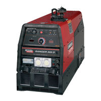
Lincoln Electric RANGER 305D SVM175-A Service Manual (195 pages)
Lincoln Electric Welder User Manual
Brand:
Lincoln Electric
| Category:
Welding System
| Size: 5.94 MB
Table of Contents
Safety
2
Return to Main Menu
6
Table of Contents
7
Installation
8
Technical Specifications
8
Safety Precautions
10
Location and Ventilation
10
Storing
10
Angle of Operation
10
Lifting
11
High Altitude Operation
11
High Temperature Operation
11
Vehicle Mounting
11
Pre-Operation Engine Service
12
Oil
12
Fuel
12
Engine Cooling System
12
Remote Control
13
Electrical Output Connections
13
Machine Grounding
13
Ranger 305D Output Connections
13
Welding Output Cables
14
Cable Installation
14
Auxiliary Power Receptacles
14
Standby Power Connections
14
Connection of Ranger 305D to Premises Wiring
16
Operation Section
17
Operating Instructions
18
Safety Instructions
18
Additional Safety
18
General Description
18
Operation
19
Design Features
19
Control and Settings
19
Engine Controls
20
Glow Plug Push Button
20
Start Push Button
20
Engine Alternator Trouble Light
20
Welding Controls
21
Output Control
21
Arc Control
21
14-Pin Amphenol
21
Engine Operation
22
Before Starting the Engine
22
Starting the Engine
22
Stopping the Engine
22
Break-In Period
23
Stick Welding
23
Constant Current Welding
23
Downhill Pipe Welding
23
Tig Welding
24
Wire Welding-CV
24
Arc Gouging
24
Auxiliary Power
24
Simultaneous Welding and Auxiliary Power Loads
25
Accessories
27
Field Installed Options
28
Tig Welding Accessories
28
Semiautomatic Fcaw and Mig Welding Accessories
28
Connection of Lincoln
29
Electric Wire Feeders
29
Connection Diagram
29
Connection of the LN-25 to the Ranger 305D
30
Across the Arc Connection Diagram
30
Connection of the LN-25 to the Ranger 305D with 42 Volt
31
Control Cable Connection Diagram
33
Maintenance
37
Routine and Periodic Maintenance
38
Engine Maintenance
38
Maintenance Schedule
39
Engine Oil Change
40
Engine Oil Refill Capacities
40
Oil Filter Change
40
Service Instructions & Installation Tips
41
Air Cleaner
42
Cooling System
42
Tightening the Fan Belt
42
Fuel System Service
43
Bleeding the Fuel System
43
Fuel Filter
43
Engine Adjustment
43
Cleaning the Battery
44
Checking the Electrolyte Level
44
Charging the Battery
44
Optional Spark Arrestor
44
GFCI Receptacle Testing and Resetting Procedure
45
Major Component Locations
46
Theory of Operation Section
47
Ranger 305D Block Logic Diagram
47
Battery
48
Engine Idle System
49
Idle Switch Operation
49
Idle Solenoid Operation
49
Generating Power
50
Flashing
50
Building Output
50
AC Output
50
Weld Power and Control
51
Weld Control and Feedback
51
Remote Output Control
52
Electronic Output Contactor
52
Digital Meters
52
Chopper Technology Fundamentals
53
IGBT Operation
54
Pulse Width Modulation
54
Minimum Output
54
Maximum Output
54
Troubleshooting & Repair Section
55
How to Use Troubleshooting Guide
56
Locate Problem
56
Perform External Tests
56
Perform Component Tests
56
PC Board Troubleshooting Procedures
57
Case Cover Removal and Replacement Procedure
75
Test Description
75
Door Removal
76
Removal Procedure
76
Replacement Procedure
76
Locking Tab
76
Chopper Module Capacitor Discahrge Procedure
77
Fuel Shutdown Solenoid Test
79
Fuel Shutdown Solenoid Location
80
Fuel Solenoid Connections
81
Engine Throttle Adjustment Test
83
Strobe Mark Location
84
Strobe-Tach Method
84
Solenoid
85
Throttle Adjustment Procedure
86
Vibratach Method
86
Low Idle Adjustment
86
High Isle Adjustment
86
Idler Solenoid Test
87
Plug(S) Pin Location
88
Engine Alterantor Test
89
Lead Locations
90
Brush and Slip Ring Service Procedure
91
Cleaning Slip Rings
92
Seating Brushes
92
Rotor Resistance and Ground Test (Static)
93
Rotor Brush Leads
94
Slip Rings
94
Rotor Voltage Test
97
Flashing Voltage Test
101
Exciter Leads T1, T2, T3
103
Oil Pressure Switch
103
Oil Filter
103
Stator Voltage Tests
105
Receptacle Lead Locations
106
To Test the 120 VAC Auxiliary Winding
106
To Test the 240 VAC Auxiliary Winding
106
Rectifier Bridge Detail
107
To Test the 120 VAC Wire Feeder Supply
107
To Test the 42 VAC Wire Feeder Winding
108
To Test the Three-Phase Weld Winding
108
Stator Short Circuit & Ground Test
109
Weld Control Board
110
Output Rectifier Bridge Test
111
Shunt/Rectifier Leads
113
Diode Test Table
114
Chopper Module Function Test
115
Power Module Connections
116
Chopper Module Resistance Test
119
Weld Control Board PWM Gate Signal Test
123
Weld Control Feedback Test
125
Control Potentiometer and Mode Switch Resistance Test
129
Pot/Mode Switch Resistance Test
131
Remote Receptacle Resistance Test
133
Amphenol 1
134
Output Rectifier Bridge and Choke Removal and Replacement
137
Removing the Output Rectifier
138
Removing the Output Choke
138
Replacing the Output Choke
138
Replacing the Output Rectifier
139
Chopper Module Removal and Replacement
141
Stator/Rotor Removal and Replacement
145
Battery Placement
146
Wire Guide Hole
147
Alternator Leads
147
Disc Ring Location
149
Removing the Rotor
149
Replacing the Rotor
149
Clamping Ring
149
Replacing the Stator
150
Normal Open Circuit Voltage Waveform
151
High Idle - no Load
151
Scope Settings
151
Normal Open Circuit Voltage Waveform (Stick)
152
Max Control Pot - High Idle - no Load
152
Normal Weld Voltage Waveform (Stick CC)
153
Machine Loaded to 300 Amps at 27 Volts
153
Normal Open Circuit Voltage Waveform (Wire CV Tap)
154
Normal Weld Voltage Waveform (Wire CV)
155
Retest after Repair
156
Engine Output
156
Welder DC (Stick) Output
156
Electrical Diagrams Section
157
Ranger 305D- Kubota - Wiring Diagram
158
Ranger 305D Ce Kubota Wiring Diagram - Uk
161
Ranger 305D Ce Kubota - Wiring Diagram - Europe
164
Ranger 305D Ce Kubota Wiring Diagram -Europe
166
Electrical Diagrams
167
Machine Schematic
168
Advertisement
Advertisement
Related Products
Lincoln Electric RANGER 305 D CE
Lincoln Electric RANGER 305D IM730
Lincoln Electric Ranger 305D CE
Lincoln Electric RANGER 305D AU
Lincoln Electric Ranger 305 G
Lincoln Electric POWERTEC 305C PRO
Lincoln Electric POWERTEC 305C Series
Lincoln Electric POWERTEC 305C 400V
Lincoln Electric POWERTEC 305S
Lincoln Electric RANGER 305LPG
Lincoln Electric Categories
Welding System
Welding Accessories
Flashlight
Wire Feeders
Portable Generator
More Lincoln Electric Manuals
Login
Sign In
OR
Sign in with Facebook
Sign in with Google
Upload manual
Upload from disk
Upload from URL