Sign In
Upload
Manuals
Brands
Lincoln Electric Manuals
Welding System
LF-72/74
Lincoln Electric LF-72/74 Wire Feeder Kit Manuals
Manuals and User Guides for Lincoln Electric LF-72/74 Wire Feeder Kit. We have
1
Lincoln Electric LF-72/74 Wire Feeder Kit manual available for free PDF download: Service Manual
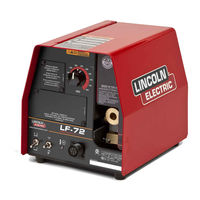
Lincoln Electric LF-72/74 Service Manual (119 pages)
Lincoln Electric Welder User Manual
Brand:
Lincoln Electric
| Category:
Welding System
| Size: 6 MB
Table of Contents
Table of Contents
7
Service Manual
1
California Proposition 65 Warnings
2
Electric and Magnetic Fields
2
Electric Shock Can Kill
3
Fumes and Gases
3
Installation Section
7
Installation
8
Technical Specifications
8
Safety Precautions
9
Location
9
Mounting
9
Bench Mount
10
Boom Mount
10
Suspended
10
Swivel Mount
10
Weld Cable Sizes
11
Coaxial Weld Cables
12
Installation
12
Weld Cable Connections
12
Analog Control Cable Connections
13
High Frequency Protection
15
Remote Sense Lead Specifications
15
Welding Gun/Wire Feeder Trigger Connector
15
Wire Drive Systems
15
Welding Guns, Torches and Accesories
16
Procedure for Changing Drive and Idle Roll Sets
17
Wire Drive Configuration
17
Pressure Arm Adjustment
18
Wire Reel Loading
19
Weld Wire Routing
20
Shielding Gas Connection
21
Installing Electrode Conduit Kits
22
Aluminum Wire Preperations
23
Typical System Configurations
25
Operation Section
27
Operation
28
Safety Precautions
28
Graphic Symbols
28
Common Welding Abbreviations
29
Product Description
29
Recommended Processes
29
Required Equipment
29
Front Panel Controls and Connections
30
5. 2 Step - Trigger Interlock Switch
31
Burnback and Postflow Timer Kit (Optional
31
Cold Feed/Gas Purge Switch
31
Remote Voltage Control Kit (Optional
31
Thermal LED, Motor Overload
31
Gun Receiver Bushing
32
Trigger Connector 5-Pin Amphenol
32
Wire Feed Speed Knob
32
Optional Kits
34
Calibration Specification
40
Periodic Maintenance
40
Routine Maintenance
40
Maintenance
43
Installation
44
Safety Precautions
45
Location
45
ELECTRIC SHOCK Can Kill
45
Mounting
45
Bench Mount
46
Swivel Mount
46
Boom Mount
46
Suspended
46
Weld Cable Sizes
47
Coaxial Weld Cables
48
Weld Cable Connections
48
Welding Gun/Wire Feeder Trigger Connector
51
High Frequency Protection
51
Remote Sense Lead Specifications
51
Wire Drive Systems
51
Welding Guns, Torches and Accessories
52
Wire Drive Configuration
53
Assembly of Drive Rolls and Wire Guides
54
Pressure Arm Adjustment
55
Shielding Gas Connection
56
Wire Reel Loading
57
Weld Wire Routing
58
Installing Electrode Conduit Kits
59
Aluminum Wire Preparations
60
Common Equipment Set-Ups
62
Table of Contents
65
Common Welding Abbreviations
66
Operation
66
Safety Precautions
66
Product Description
67
Front Panel Controls and Connections
68
Wire Feed Speed Knob
69
Remote Voltage Control Kit (Optional
69
Burnback and Postflow Timer Kit (Optional
69
Thermal LED, Motor Overload
69
Cold Feed/Gas Purge Switch
69
Step - Trigger Interlock Switch
70
Gun Receiver Bushing
70
Trigger Connector 5-Pin Amphenol
70
Optional Kits
72
General Description
82
Input Receptacle, Control Board and Operator Con- Trols
82
Theory of Operation
82
Control Board
83
Table of Contents
85
Troubleshooting & Repair Section
85
How to Use Troubleshooting Guide
86
Troubleshooting and Repair
86
Pc Board Troubleshooting Procedures
87
Function Problems
88
Drive Motor and Tach Feedback Test
91
Materials Needed
91
Test Description
91
Gas Solenoid Test
93
Test Procedure
94
Diode Bridge Test
95
Wire Speed Potentiometer Test
97
PC Board Removal and Replacement
99
Removal Procedure
100
Replacement Procedure
100
Wire Drive Motor and Gear Box
101
Troubleshooting and Repair
102
Wire Drive Motor and Gear Box Removal and Replacement
102
Retest after Repair
105
Operation Verification
105
Table of Contents
107
Electrical Diagrams Section
107
Electrical Diagrams
109
Wiring Diagram - Entire Machine - Code 11209, 11210, 11211,11227 (L12146-1
109
Wiring Diagram - Entire Machine - Code 11290, 11291, 11292,11293 (L12146-2
110
Wiring Diagram - Entire Machine - Code 11195, 11196, 11197, (L12484
111
Schematic - Entire Machine - Code 11075, 11076, 11077 (G4617
112
Schematic - Entire Machine - Code 11209, 11210, 11211,11227 (G4617-1
113
Schematic - Entire Machine - Code 11290, 11291, 11292,11293 (G4617-2
114
Schematic - Entire Machine - Code 11195, 11196, 11197, (G4942
115
Schematic - Common Analog Control PC Board - (G4559 Sheet 1
116
Schematic - Common Analog Control PC Board - (G4559 Sheet 2
117
Schematic - Common Analog Control PC Board - (G4559 Sheet 3
118
PC Board Assembly - Common Analog Control - (G4560-2E0
119
Advertisement
Advertisement
Related Products
Lincoln Electric LF-72
Lincoln Electric LF-74
Lincoln Electric LF 52D
Lincoln Electric LF 56D
Lincoln Electric LF 33S
Lincoln Electric LF 5D ADVANCED
Lincoln Electric LF 5D STANDARD
Lincoln Electric LF 5D STANDARD GFR
Lincoln Electric Jetweld LH-73
Lincoln Electric LINC 406
Lincoln Electric Categories
Welding System
Welding Accessories
Flashlight
Wire Feeders
Portable Generator
More Lincoln Electric Manuals
Login
Sign In
OR
Sign in with Facebook
Sign in with Google
Upload manual
Upload from disk
Upload from URL