Sign In
Upload
Manuals
Brands
Leviton Manuals
Dimmer
a-2000
Leviton a-2000 Manuals
Manuals and User Guides for Leviton a-2000. We have
1
Leviton a-2000 manual available for free PDF download: User Manual
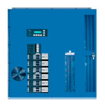
Leviton a-2000 User Manual (85 pages)
DIMMER CABINET WITH DIGITAL CONTROLS 12 & 24 CIRCUIT VERSIONS
Brand:
Leviton
| Category:
Dimmer
| Size: 3 MB
Table of Contents
User Guide
1
Table of Contents
3
Overview
7
Inspection
7
Updates
7
Description
7
Dimmer Cabinets with Digital Controls Revision G November
7
Control Overview
8
Mounting - Surface or Flush Mounted
8
Stacked Mounting
8
Cooling Fans
8
Feed and Load Wiring
9
Control Input Wiring
9
Fluorescent Wiring
9
Turn on
9
Bypass Switch - Non Universal 120V Units Only
9
Bypass Shunts - Non Universal 277V Units Only
9
Bypass Switch-Universal Units Only
10
Modules
10
Checklist
10
Warnings
11
Installation
12
Installation Checklist - Non Universal 120V Units
12
Installation Checklist - Non Universal 277V and Universal Units
12
Step 1: Mounting
13
Step 1A -Surface Mount
13
Flush Mount
14
Step 1B - Flush Mount Frames
14
Main Feed and Load Wiring
16
Step 2: Power Wiring - Feed\Line Wiring
16
Step 3: Load Circuit Wiring - 120 Volt Units
20
Step 4 - Relay Cabinet (OPTIONAL)
23
Low Voltage Control Wiring
25
Step 5: Control Input Wiring
25
Luma-Net® III
26
Power Considerations for Control Systems
26
Power Requirements & Maximum Run Length
26
Power Wire - Run Length
28
Terminating the Wiring
28
Wiring the Phoenix Connector
31
Special Feature for Low Voltage Power Terminations
32
Testing the Wiring
33
DMX-512
34
DMX Wire Recommendation
34
Analog Input, 0-10 VDC (Optional)
35
Photocell Input
35
Multiple Signal Types
37
External Full On/Emergency (Full Bright)
38
Step 6: Fluorescent Dimming and Control Output Wiring
40
Types of Dimming Ballasts
40
Other Ballast Types
41
Dimmer Module Installation
42
Step 7: Dimmer Module Installation And/Or Replacement
42
Blanking Plates
42
Removal or Installation of Dimmer Module
43
To Remove a Dimmer Module
43
To Install a Dimmer Module into One of the Positions
43
Step 8: Bypass Mode
45
Set 120 V Non Universal Dimmers to Bypass Mode
45
277V Non Universal Bypass
46
Universal Bypass
46
Step 9: Double Check the Wiring
47
Step 10: Turn on the Power
47
Step 11: Clear Faults that Have Caused any Breakers to Trip
47
Step 12: 120 V Systems - Set Bypass Switches to Normal
47
Digital Control Panel
48
Readouts and Indicators
48
LCD Display
48
Programming/Function Buttons
48
LED Indicators
48
Navigation Buttons
49
Step 13: Configuration and Programming
50
LCD Display Menu Structures
50
Basic Concepts
55
Step 13A: Display at Startup
56
Potential Error Screens in the Main Menu
56
To Auto Assign Module Types
56
Step 13B: Verifying Phase Voltages
56
Step 13C: Assigning Module Types
56
Assign the Module/Load Type
59
Step 13D: Modify the Dimmer Type Features
60
Step 13E: Verifying Module Programming in a Dimmer Cabinet
62
Step 13F: Assigning Luma-Net And/Or DMX512 Channels
63
Assigning Numbers Automatically
63
Assigning Individual Control Channels
63
Verifying Assignment of Mark VII Analog Output Signal
64
Step 13G: Daylight Harvesting/Photocells
64
Background-Daylighting
64
Background-Photocells
65
Configuring Your A-2000 Cabinet to Use a Photocell
65
For Example, to Use this Feature Given the Following Installation
67
To Enable the Dimmer for Photocell Control
67
Step: 13H: Modifying Factory Defaults
67
Luma-Net Restore
68
Line Regulation
68
Parts Replacement
69
Specifications
70
Appendix A
71
Control Inputs
71
Luma-Net® III
71
Dmx512
71
Analog
71
Multiple Signal Types
71
Types of Dimmer Modules
72
Dual Dimmer Module 000-A20DD-012(120V), -A27 (120/277V)
72
Constant Module 000-A20DC-012 (120V), -A27 (120/277V)
72
High Rise Time Module 000-A20HD-012
72
Dual Universal Module 000-A20UN-012(120V), -027 (120/277V)
73
Fluorescent Dimming Ballast Types
73
0-10 VDC Controlled Ballasts
73
Two-Wire Fluorescent Ballasts (Additional Control Wiring Is Not Required)
74
Other Ballasts - Three-Wire- (Refer to the Load Wiring Schematic.)
74
Warranty Information
76
Limited Warranty
76
Power Considerations for Control Systems
79
Terminology
79
Power Requirements & Maximum Run Length
79
Power Wire - Run Length
84
Advertisement
Advertisement
Related Products
Leviton AEN24
Leviton AESS5
Leviton AEHTK
Leviton A8332
Leviton A8812
Leviton A7810
Leviton A8810-PS1
Leviton EMB HubLite A7810-PS1
Leviton VerifEye A8911
Leviton VerifEye A8911-PS1
Leviton Categories
Accessories
Switch
Dimmer
Controller
Cables and connectors
More Leviton Manuals
Login
Sign In
OR
Sign in with Facebook
Sign in with Google
Upload manual
Upload from disk
Upload from URL