Sign In
Upload
Manuals
Brands
LevelOne Manuals
Switch
GTL-2882
LevelOne GTL-2882 Manuals
Manuals and User Guides for LevelOne GTL-2882. We have
2
LevelOne GTL-2882 manuals available for free PDF download: User Manual, Quick Installation Manual
LevelOne GTL-2882 User Manual (706 pages)
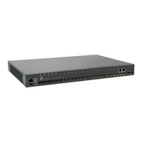
28-Port Stackable Layer 3 Lite Managed Gigabit Switch
Brand:
LevelOne
| Category:
Switch
| Size: 19.94 MB
Table of Contents
User Manual
1
How to Use this Guide
3
Contents
5
Table of Contents
5
Figures
17
Tables
31
Section I
33
Getting Started
33
1 Introduction
35
Key Features
35
Table 1: Key Features
35
Description of Software Features
37
IP Routing
41
Equal-Cost Multipath Load Balancing
42
Address Resolution Protocol
42
Operation, Administration, and Maintenance
42
System Defaults
43
Table 2: System Defaults
43
Web Configuration
47
2 Using the Web Interface
49
Connecting to the Web Interface
49
Navigating the Web Browser Interface
50
Home Page
50
Figure 1: Home Page
50
Configuration Options
51
Panel Display
51
Figure 2: Front Panel Indicators
51
Table 3: Web Page Configuration Buttons
51
Main Menu
52
Table 4: Switch Main Menu
52
3 Basic Management Tasks
71
Displaying System Information
72
Figure 3: System Information
72
Displaying Hardware/Software Versions
73
Configuring Support for Jumbo Frames
74
Figure 4: General Switch Information
74
Displaying Bridge Extension Capabilities
75
Figure 5: Configuring Support for Jumbo Frames
75
Figure 6: Displaying Bridge Extension Configuration
76
Managing System Files
77
Copying Files Via FTP/TFTP or HTTP
77
Saving the Running Configuration to a Local File
79
Figure 7: Copy Firmware
79
Setting the Start-Up File
80
Figure 8: Saving the Running Configuration
80
Figure 9: Setting Start-Up Files
80
Showing System Files
81
Automatic Operation Code Upgrade
81
Figure 10: Displaying System Files
81
Setting the System Clock
85
Figure 11: Configuring Automatic Code Upgrade
85
Figure 12: Manually Setting the System Clock
86
Setting the Time Manually
86
Configuring NTP
87
Figure 13: Setting the Polling Interval for SNTP
87
Setting the SNTP Polling Interval
87
Configuring Time Servers
88
Figure 14: Configuring NTP
88
Figure 15: Specifying SNTP Time Servers
89
Figure 16: Adding an NTP Time Server
90
Figure 17: Showing the NTP Time Server List
90
Figure 18: Adding an NTP Authentication Key
91
Figure 19: Showing the NTP Authentication Key List
92
Setting the Time Zone
92
Configuring Summer Time
93
Figure 20: Setting the Time Zone
93
Table 5: Predefined Summer-Time Parameters
94
Configuring the Console Port
95
Figure 21: Configuring Summer Time
95
Figure 22: Console Port Settings
96
Configuring Telnet Settings
97
Displaying CPU Utilization
98
Figure 23: Telnet Connection Settings
98
Displaying Memory Utilization
99
Figure 24: Displaying CPU Utilization
99
Figure 25: Displaying Memory Utilization
99
Stacking
100
Setting the Master Unit
100
Enabling Stacking Ports
101
Figure 26: Setting the Stack Master
101
Renumbering the Stack
102
Figure 27: Enabling Stacking on 10G Ports
102
Figure 28: Renumbering the Stack
102
Resetting the System
103
Figure 29: Restarting the Switch (Immediately)
105
Figure 30: Restarting the Switch (In)
105
Figure 31: Restarting the Switch (At)
106
Figure 32: Restarting the Switch (Regularly)
106
4 Interface Configuration
107
Port Configuration
108
Configuring by Port List
108
Figure 33: Configuring Connections by Port List
110
Configuring by Port Range
111
Displaying Connection Status
111
Figure 34: Configuring Connections by Port Range
111
Configuring Local Port Mirroring
112
Figure 35: Displaying Port Information
112
Figure 36: Configuring Local Port Mirroring
112
Configuring Remote Port Mirroring
114
Figure 37: Configuring Local Port Mirroring
114
Figure 38: Displaying Local Port Mirror Sessions
114
Figure 39: Configuring Remote Port Mirroring
115
Figure 40: Configuring Remote Port Mirroring (Source)
118
Figure 41: Configuring Remote Port Mirroring (Intermediate)
118
Figure 42: Configuring Remote Port Mirroring (Destination)
118
Showing Port or Trunk Statistics
119
Table 6: Port Statistics
119
Figure 43: Showing Port Statistics (Table)
122
Displaying Transceiver Data
123
Figure 44: Showing Port Statistics (Chart)
123
Configuring Transceiver Thresholds
124
Figure 45: Displaying Transceiver Data
124
Performing Cable Diagnostics
126
Figure 46: Configuring Transceiver Thresholds
126
Trunk Configuration
128
Figure 47: Performing Cable Tests
128
Configuring a Static Trunk
129
Figure 48: Configuring Static Trunks
129
Figure 49: Creating Static Trunks
130
Figure 50: Adding Static Trunks Members
131
Figure 51: Configuring Connection Parameters for a Static Trunk
131
Configuring a Dynamic Trunk
132
Figure 52: Showing Information for Static Trunks
132
Figure 53: Configuring Dynamic Trunks
132
Figure 54: Configuring the LACP Aggregator Admin Key
135
Figure 55: Enabling LACP on a Port
136
Figure 56: Configuring LACP Parameters on a Port
136
Figure 57: Showing Members of a Dynamic Trunk
137
Figure 58: Configuring Connection Settings for a Dynamic Trunk
137
Displaying LACP Port Counters
138
Figure 59: Showing Connection Parameters for Dynamic Trunks
138
Table 7: LACP Port Counters
138
Displaying LACP Settings and Status for the Local Side
139
Figure 60: Displaying LACP Port Counters
139
Table 8: LACP Internal Configuration Information
139
Figure 61: Displaying LACP Port Internal Information
140
Displaying LACP Settings and Status for the Remote Side
141
Table 9: LACP Remote Device Configuration Information
141
Configuring Load Balancing
142
Figure 62: Displaying LACP Port Remote Information
142
Figure 63: Configuring Load Balancing
143
Saving Power
144
Figure 64: Enabling Power Savings
145
Traffic Segmentation
146
Enabling Traffic Segmentation
146
Configuring Uplink and Downlink Ports
147
Figure 65: Enabling Traffic Segmentation
147
Table 10: Traffic Segmentation Forwarding
147
Figure 66: Configuring Members for Traffic Segmentation
148
VLAN Trunking
149
Figure 67: Showing Traffic Segmentation Members
149
Figure 68: Configuring VLAN Trunking
149
Figure 69: Configuring VLAN Trunking
151
5 VLAN Configuration
153
IEEE 802.1Q Vlans
153
Figure 70: VLAN Compliant and VLAN Non-Compliant Devices
155
Configuring VLAN Groups
156
Figure 71: Using GVRP
156
Figure 72: Creating Static Vlans
158
Figure 73: Modifying Settings for Static Vlans
158
Adding Static Members to Vlans
159
Figure 74: Showing Static Vlans
159
Figure 75: Configuring Static Members by VLAN Index
162
Figure 76: Configuring Static VLAN Members by Interface
162
Configuring Dynamic VLAN Registration
163
Figure 77: Configuring Static VLAN Members by Interface Range
163
Figure 78: Configuring Global Status of GVRP
165
Figure 79: Configuring GVRP for an Interface
165
IEEE 802.1Q Tunneling
166
Figure 80: Showing Dynamic Vlans Registered on the Switch
166
Figure 81: Showing the Members of a Dynamic VLAN
166
Figure 82: Qinq Operational Concept
167
Enabling Qinq Tunneling on the Switch
170
Figure 83: Enabling Qinq Tunneling
171
Creating CVLAN to SPVLAN Mapping Entries
172
Adding an Interface to a Qinq Tunnel
173
Figure 84: Configuring CVLAN to SPVLAN Mapping Entries
173
Figure 85: Showing CVLAN to SPVLAN Mapping Entries
173
Figure 86: Adding an Interface to a Qinq Tunnel
174
Protocol Vlans
175
Configuring Protocol VLAN Groups
175
Figure 87: Configuring Protocol Vlans
176
Mapping Protocol Groups to Interfaces
177
Figure 88: Displaying Protocol Vlans
177
Figure 89: Assigning Interfaces to Protocol Vlans
178
Configuring IP Subnet Vlans
179
Figure 90: Showing the Interface to Protocol Group Mapping
179
Figure 91: Configuring IP Subnet Vlans
180
Configuring MAC-Based Vlans
181
Figure 92: Showing IP Subnet Vlans
181
Figure 93: Configuring MAC-Based Vlans
182
Configuring VLAN Mirroring
183
Figure 94: Showing MAC-Based Vlans
183
Figure 95: Configuring VLAN Mirroring
184
Figure 96: Showing the Vlans to Mirror
184
Configuring VLAN Translation
185
Figure 97: Configuring VLAN Translation
185
Figure 98: Configuring VLAN Translation
186
Figure 99: Showing the Entries for VLAN Translation
186
6 Address Table Settings
187
Configuring MAC Address Learning
187
Figure 100: Configuring MAC Address Learning
188
Setting Static Addresses
189
Figure 101: Configuring Static MAC Addresses
190
Figure 102: Displaying Static MAC Addresses
190
Changing the Aging Time
191
Displaying the Dynamic Address Table
191
Figure 103: Setting the Address Aging Time
191
Figure 104: Displaying the Dynamic MAC Address Table
192
Clearing the Dynamic Address Table
193
Figure 105: Clearing Entries in the Dynamic MAC Address Table
193
Configuring MAC Address Mirroring
194
Issuing MAC Address Traps
195
Figure 106: Mirroring Packets Based on the Source MAC Address
195
Figure 107: Showing the Source MAC Addresses to Mirror
195
Figure 108: Issuing MAC Address Traps (Global Configuration)
196
Figure 109: Issuing MAC Address Traps (Interface Configuration)
196
7 Spanning Tree Algorithm
197
Overview
197
Figure 110: STP Root Ports and Designated Ports
198
Figure 111: MSTP Region, Internal Spanning Tree, Multiple Spanning Tree
198
Configuring Loopback Detection
199
Figure 112: Spanning Tree - Common Internal, Common, Internal
199
Configuring Global Settings for STA
201
Figure 113: Configuring Port Loopback Detection
201
Figure 114: Configuring Global Settings for STA (STP)
205
Figure 115: Configuring Global Settings for STA (RSTP)
205
Displaying Global Settings for STA
206
Figure 116: Configuring Global Settings for STA (MSTP)
206
Configuring Interface Settings for STA
207
Figure 117: Displaying Global Settings for STA
207
Table 11: Recommended STA Path Cost Range
208
Figure 118: Determining the Root Port
209
Table 12: Default STA Path Costs
209
Figure 119: Configuring Interface Settings for STA
211
Displaying Interface Settings for STA
212
Figure 120: STA Port Roles
213
Configuring Multiple Spanning Trees
214
Figure 121: Displaying Interface Settings for STA
214
Figure 122: Creating an MST Instance
216
Figure 123: Displaying MST Instances
216
Figure 124: Modifying the Priority for an MST Instance
217
Figure 125: Displaying Global Settings for an MST Instance
217
Figure 126: Adding a VLAN to an MST Instance
218
Figure 127: Displaying Members of an MST Instance
218
Configuring Interface Settings for MSTP
219
Figure 128: Configuring MSTP Interface Settings
220
Figure 129: Displaying MSTP Interface Settings
220
8 Congestion Control
221
Rate Limiting
221
Storm Control
222
Figure 130: Configuring Rate Limits
222
Automatic Traffic Control
224
Figure 131: Configuring Storm Control
224
Figure 132: Storm Control by Limiting the Traffic Rate
224
Figure 133: Storm Control by Shutting down a Port
225
Setting the ATC Timers
225
Figure 134: Configuring ATC Timers
226
Configuring ATC Thresholds and Responses
227
Figure 135: Configuring ATC Interface Attributes
229
9 Class of Service
231
Layer 2 Queue Settings
231
Setting the Default Priority for Interfaces
231
Figure 136: Setting the Default Port Priority
232
Selecting the Queue Mode
232
Figure 137: Setting the Queue Mode (Strict)
234
Figure 138: Setting the Queue Mode (WRR)
234
Figure 139: Setting the Queue Mode (Strict and WRR)
235
Mapping Cos Values to Egress Queues
235
Table 13: IEEE 802.1P Egress Queue Priority Mapping
235
Table 14: Cos Priority Levels
236
Table 15: Mapping Internal Per-Hop Behavior to Hardware Queues
236
Figure 140: Mapping Cos Values to Egress Queues
237
Figure 141: Showing Cos Values to Egress Queue Mapping
237
Layer 3/4 Priority Settings
238
Setting Priority Processing to DSCP or Cos
238
Figure 142: Setting the Trust Mode
239
Mapping Ingress DSCP Values to Internal DSCP Values
239
Table 16: Default Mapping of DSCP Values to Internal Phb/Drop Values
240
Figure 143: Configuring DSCP to DSCP Internal Mapping
241
Figure 144: Showing DSCP to DSCP Internal Mapping
241
Mapping Cos Priorities to Internal DSCP Values
242
Table 17: Default Mapping of Cos/Cfi to Internal Phb/Drop Precedence
242
Figure 145: Configuring Cos to DSCP Internal Mapping
243
Figure 146: Showing Cos to DSCP Internal Mapping
244
10 Quality of Service
245
Overview
245
Configuring a Class Map
246
Figure 147: Configuring a Class Map
248
Figure 148: Showing Class Maps
248
Figure 149: Adding Rules to a Class Map
249
Figure 150: Showing the Rules for a Class Map
249
Creating Qos Policies
250
Figure 151: Configuring a Policy Map
257
Figure 152: Showing Policy Maps
257
Figure 153: Adding Rules to a Policy Map
258
Attaching a Policy Map to a Port
259
Figure 154: Showing the Rules for a Policy Map
259
Figure 155: Attaching a Policy Map to a Port
260
11 Voip Traffic Configuration
261
Overview
261
Configuring Voip Traffic
262
Configuring Telephony OUI
263
Figure 156: Configuring a Voice VLAN
263
Configuring Voip Traffic Ports
264
Figure 157: Configuring an OUI Telephony List
264
Figure 158: Showing an OUI Telephony List
264
Figure 159: Configuring Port Settings for a Voice VLAN
266
12 Security Measures
267
AAA (Authentication, Authorization and Accounting)
268
Configuring Local/Remote Logon Authentication
269
Configuring Remote Logon Authentication Servers
270
Figure 160: Configuring the Authentication Sequence
270
Figure 161: Authentication Server Operation
270
Figure 162: Configuring Remote Authentication Server (RADIUS)
273
Figure 163: Configuring Remote Authentication Server (TACACS+)
274
Figure 164: Configuring AAA Server Groups
274
Configuring AAA Accounting
275
Figure 165: Showing AAA Server Groups
275
Figure 166: Configuring Global Settings for AAA Accounting
277
Figure 167: Configuring AAA Accounting Methods
278
Figure 168: Showing AAA Accounting Methods
279
Figure 169: Configuring AAA Accounting Service for 802.1X Service
279
Figure 170: Configuring AAA Accounting Service for Command Service
280
Figure 171: Configuring AAA Accounting Service for Exec Service
280
Configuring AAA Authorization
281
Figure 172: Displaying a Summary of Applied AAA Accounting Methods
281
Figure 173: Displaying Statistics for AAA Accounting Sessions
281
Figure 174: Configuring AAA Authorization Methods
283
Figure 175: Showing AAA Authorization Methods
283
Configuring User Accounts
284
Figure 176: Configuring AAA Authorization Methods for Exec Service
284
Figure 177: Displaying the Applied AAA Authorization Method
284
Web Authentication
286
Figure 178: Configuring User Accounts
286
Figure 179: Showing User Accounts
286
Configuring Global Settings for Web Authentication
287
Configuring Interface Settings for Web Authentication
288
Figure 180: Configuring Global Settings for Web Authentication
288
Network Access (MAC Address Authentication)
289
Figure 181: Configuring Interface Settings for Web Authentication
289
Table 18: Dynamic Qos Profiles
290
Configuring Global Settings for Network Access
291
Configuring Network Access for Ports
292
Figure 182: Configuring Global Settings for Network Access
292
Configuring Port Link Detection
294
Figure 183: Configuring Interface Settings for Network Access
294
Configuring a MAC Address Filter
295
Figure 184: Configuring Link Detection for Network Access
295
Figure 185: Configuring a MAC Address Filter for Network Access
296
Displaying Secure MAC Address Information
297
Figure 186: Showing the MAC Address Filter Table for Network Access
297
Figure 187: Showing Addresses Authenticated for Network Access
298
Configuring HTTPS
299
Configuring Global Settings for HTTPS
299
Table 19: HTTPS System Support
299
Replacing the Default Secure-Site Certificate
300
Figure 188: Configuring HTTPS
300
Configuring the Secure Shell
302
Figure 189: Downloading the Secure-Site Certificate
302
Configuring the SSH Server
304
Figure 190: Configuring the SSH Server
305
Figure 191: Generating the SSH Host Key Pair
306
Generating the Host Key Pair
306
Figure 192: Showing the SSH Host Key Pair
307
Importing User Public Keys
307
Figure 193: Copying the SSH User's Public Key
308
Access Control Lists
309
Figure 194: Showing the SSH User's Public Key
309
Setting a Time Range
310
Figure 195: Setting the Name of a Time Range
311
Figure 196: Showing a List of Time Ranges
312
Figure 197: Add a Rule to a Time Range
312
Figure 198: Showing the Rules Configured for a Time Range
313
Showing TCAM Utilization
313
Figure 199: Showing TCAM Utilization
314
Setting the ACL Name and Type
314
Figure 200: Creating an ACL
315
Figure 201: Showing a List of Acls
315
Configuring a Standard Ipv4 ACL
316
Configuring an Extended Ipv4 ACL
317
Figure 202: Configuring a Standard Ipv4 ACL
317
Configuring a Standard Ipv6 ACL
319
Figure 203: Configuring an Extended Ipv4 ACL
319
Figure 204: Configuring a Standard Ipv6 ACL
320
Configuring an Extended Ipv6 ACL
321
Figure 205: Configuring an Extended Ipv6 ACL
322
Configuring a MAC ACL
323
Figure 206: Configuring a MAC ACL
324
Configuring an ARP ACL
325
Binding a Port to an Access Control List
326
Figure 207: Configuring a ARP ACL
326
Configuring ACL Mirroring
327
Figure 208: Binding a Port to an ACL
327
Figure 209: Configuring ACL Mirroring
328
Showing ACL Hardware Counters
329
Figure 210: Showing the Vlans to Mirror
329
ARP Inspection
330
Figure 211: Showing ACL Statistics
330
Configuring Global Settings for ARP Inspection
331
Configuring VLAN Settings for ARP Inspection
333
Figure 212: Configuring Global Settings for ARP Inspection
333
Figure 213: Configuring VLAN Settings for ARP Inspection
334
Configuring Interface Settings for ARP Inspection
335
Figure 214: Configuring Interface Settings for ARP Inspection
335
Displaying ARP Inspection Statistics
336
Table 20: ARP Inspection Statistics
336
Displaying the ARP Inspection Log
337
Figure 215: Displaying Statistics for ARP Inspection
337
Table 21: ARP Inspection Log
337
Filtering IP Addresses for Management Access
338
Figure 216: Displaying the ARP Inspection Log
338
Figure 217: Creating an IP Address Filter for Management Access
339
Configuring Port Security
340
Figure 218: Showing IP Addresses Authorized for Management Access
340
Configuring 802.1X Port Authentication
342
Figure 219: Configuring Port Security
342
Figure 220: Configuring Port Authentication
343
Configuring 802.1X Global Settings
344
Configuring Port Authenticator Settings for 802.1X
345
Figure 221: Configuring Global Settings for 802.1X Port Authentication
345
Figure 222: Configuring Interface Settings for 802.1X Port Authenticator
349
Configuring Port Supplicant Settings for 802.1X
350
Figure 223: Configuring Interface Settings for 802.1X Port Supplicant
351
Displaying 802.1X Statistics
352
Table 22: 802.1X Statistics
352
Figure 224: Showing Statistics for 802.1X Port Authenticator
353
Dos Protection
354
Figure 225: Showing Statistics for 802.1X Port Supplicant
354
Figure 226: Protecting against Dos Attacks
356
Ipv4 Source Guard
357
Configuring Ports for Ipv4 Source Guard
357
Configuring Static Bindings for Ipv4 Source Guard
359
Figure 227: Setting the Filter Type for Ipv4 Source Guard
359
Figure 228: Configuring Static Bindings for Ipv4 Source Guard
361
Figure 229: Displaying Static Bindings for Ipv4 Source Guard
361
Displaying Information for Dynamic Ipv4 Source Guard Bindings
362
Ipv6 Source Guard
363
Configuring Ports for Ipv6 Source Guard
363
Figure 230: Showing the Ipv4 Source Guard Binding Table
363
Configuring Static Bindings for Ipv6 Source Guard
365
Figure 231: Setting the Filter Type for Ipv6 Source Guard
365
Figure 232: Configuring Static Bindings for Ipv6 Source Guard
367
Figure 233: Displaying Static Bindings for Ipv6 Source Guard
367
Displaying Information for Dynamic Ipv6 Source Guard Bindings
368
DHCP Snooping
369
Figure 234: Showing the Ipv6 Source Guard Binding Table
369
DHCP Snooping Global Configuration
371
DHCP Snooping VLAN Configuration
373
Figure 235: Configuring Global Settings for DHCP Snooping
373
Configuring Ports for DHCP Snooping
374
Figure 236: Configuring DHCP Snooping on a VLAN
374
Displaying DHCP Snooping Binding Information
375
Figure 237: Configuring the Port Mode for DHCP Snooping
375
Figure 238: Displaying the Binding Table for DHCP Snooping
376
13 Basic Administration Protocols
377
Configuring Event Logging
378
System Log Configuration
378
Table 23: Logging Levels
378
Figure 239: Configuring Settings for System Memory Logs
379
Remote Log Configuration
380
Figure 240: Showing Error Messages Logged to System Memory
380
Sending Simple Mail Transfer Protocol Alerts
381
Figure 241: Configuring Settings for Remote Logging of Error Messages
381
Figure 242: Configuring SMTP Alert Messages
382
Link Layer Discovery Protocol
383
Setting LLDP Timing Attributes
383
Configuring LLDP Interface Attributes
385
Figure 243: Configuring LLDP Timing Attributes
385
Figure 244: Configuring LLDP Interface Attributes
388
Configuring LLDP Interface CIVIC-Address
389
Table 24: LLDP MED Location CA Types
389
Figure 245: Configuring the CIVIC Address for an LLDP Interface
390
Figure 246: Showing the CIVIC Address for an LLDP Interface
390
Displaying LLDP Local Device Information
391
Table 25: Chassis ID Subtype
391
Table 26: System Capabilities
391
Table 27: Port ID Subtype
392
Figure 247: Displaying Local Device Information for LLDP (General)
393
Displaying LLDP Remote Device Information
394
Figure 248: Displaying Local Device Information for LLDP (Port)
394
Figure 249: Displaying Local Device Information for LLDP (Port Details)
394
Table 28: Remote Port Auto-Negotiation Advertised Capability
396
Figure 250: Displaying Remote Device Information for LLDP (Port)
401
Figure 251: Displaying Remote Device Information for LLDP (Port Details)
402
Displaying Device Statistics
403
Figure 252: Displaying Remote Device Information for LLDP (End Node)
403
Simple Network Management Protocol
405
Figure 253: Displaying LLDP Device Statistics (General)
405
Figure 254: Displaying LLDP Device Statistics (Port)
405
Table 29: Snmpv3 Security Models and Levels
406
Configuring Global Settings for SNMP
407
Figure 255: Configuring Global Settings for SNMP
408
Setting the Local Engine ID
408
Figure 256: Configuring the Local Engine ID for SNMP
409
Specifying a Remote Engine ID
409
Figure 257: Configuring a Remote Engine ID for SNMP
410
Figure 258: Showing Remote Engine Ids for SNMP
410
Setting Snmpv3 Views
411
Figure 259: Creating an SNMP View
412
Figure 260: Showing SNMP Views
412
Configuring Snmpv3 Groups
413
Figure 261: Adding an OID Subtree to an SNMP View
413
Figure 262: Showing the OID Subtree Configured for SNMP Views
413
Figure 263: Creating an SNMP Group
418
Figure 264: Showing SNMP Groups
418
Figure 265: Setting Community Access Strings
419
Setting Community Access Strings
419
Configuring Local Snmpv3 Users
420
Figure 266: Showing Community Access Strings
420
Figure 267: Configuring Local Snmpv3 Users
422
Figure 268: Showing Local Snmpv3 Users
422
Configuring Remote Snmpv3 Users
423
Figure 269: Changing a Local Snmpv3 User Group
423
Figure 270: Configuring Remote Snmpv3 Users
425
Figure 271: Showing Remote Snmpv3 Users
425
Specifying Trap Managers
426
Figure 272: Configuring Trap Managers (Snmpv1)
429
Figure 273: Configuring Trap Managers (Snmpv2C)
429
Figure 274: Configuring Trap Managers (Snmpv3)
429
Creating SNMP Notification Logs
430
Figure 275: Showing Trap Managers
430
Figure 276: Creating SNMP Notification Logs
431
Figure 277: Showing SNMP Notification Logs
432
Showing SNMP Statistics
432
Figure 278: Showing SNMP Statistics
433
Remote Monitoring
434
Configuring RMON Alarms
434
Figure 279: Configuring an RMON Alarm
436
Figure 280: Showing Configured RMON Alarms
436
Configuring RMON Events
437
Figure 281: Configuring an RMON Event
438
Configuring RMON History Samples
439
Figure 282: Showing Configured RMON Events
439
Figure 283: Configuring an RMON History Sample
440
Figure 284: Showing Configured RMON History Samples
441
Figure 285: Showing Collected RMON History Samples
441
Configuring RMON Statistical Samples
442
Figure 286: Configuring an RMON Statistical Sample
443
Figure 287: Showing Configured RMON Statistical Samples
443
Switch Clustering
444
Figure 288: Showing Collected RMON Statistical Samples
444
Configuring General Settings for Clusters
445
Cluster Member Configuration
446
Figure 289: Configuring a Switch Cluster
446
Figure 290: Configuring a Cluster Members
447
Figure 291: Showing Cluster Members
447
Figure 292: Showing Cluster Candidates
448
Managing Cluster Members
448
Ethernet Ring Protection Switching
449
Figure 293: Managing a Cluster Member
449
Figure 294: ERPS Ring Components
450
Figure 295: Ring Interconnection Architecture (Multi-Ring/Ladder Network)
452
ERPS Global Configuration
453
ERPS Ring Configuration
454
Figure 296: Setting ERPS Global Status
454
Figure 297: Sub-Ring with Virtual Channel
463
Figure 298: Sub-Ring Without Virtual Channel
464
Figure 299: Non-ERPS Device Protection
465
Figure 300: Creating an ERPS Ring
468
Figure 301: Creating an ERPS Ring
469
Figure 302: Showing Configured ERPS Rings
469
ERPS Forced and Manual Mode Operations
470
Table 31: ERPS Request/State Priority
471
Connectivity Fault Management
474
Figure 303: Blocking an ERPS Ring Port
474
Figure 304: Single CFM Maintenance Domain
475
Figure 305: Multiple CFM Maintenance Domains
476
Configuring Global Settings for CFM
478
Figure 306: Configuring Global Settings for CFM
480
Configuring CFM Maintenance Domains
481
Configuring Interfaces for CFM
481
Figure 307: Configuring Interfaces for CFM
481
Table 32: Remote MEP Priority Levels
483
Table 33: MEP Defect Descriptions
483
Figure 308: Configuring Maintenance Domains
485
Figure 309: Showing Maintenance Domains
485
Configuring CFM Maintenance Associations
486
Figure 310: Configuring Detailed Settings for Maintenance Domains
486
Figure 311: Creating Maintenance Associations
489
Figure 312: Showing Maintenance Associations
489
Configuring Maintenance End Points
490
Figure 313: Configuring Detailed Settings for Maintenance Associations
490
Figure 314: Configuring Maintenance End Points
491
Configuring Remote Maintenance End Points
492
Figure 315: Showing Maintenance End Points
492
Figure 316: Configuring Remote Maintenance End Points
493
Figure 317: Showing Remote Maintenance End Points
494
Transmitting Link Trace Messages
494
Figure 318: Transmitting Link Trace Messages
496
Transmitting Loop Back Messages
496
Figure 319: Transmitting Loopback Messages
497
Transmitting Delay-Measure Requests
498
Figure 320: Transmitting Delay-Measure Messages
499
Displaying Local Meps
500
Figure 321: Showing Information on Local Meps
500
Displaying Details for Local Meps
501
Figure 322: Showing Detailed Information on Local Meps
502
Displaying Local Mips
503
Figure 323: Showing Information on Local Mips
503
Displaying Remote Meps
504
Figure 324: Showing Information on Remote Meps
504
Displaying Details for Remote Meps
505
Figure 325: Showing Detailed Information on Remote Meps
506
Displaying the Link Trace Cache
507
Displaying Fault Notification Settings
508
Figure 326: Showing the Link Trace Cache
508
Displaying Continuity Check Errors
509
Figure 327: Showing Settings for the Fault Notification Generator
509
OAM Configuration
510
Enabling OAM on Local Ports
510
Figure 328: Showing Continuity Check Errors
510
Table 34: OAM Operation State
511
Displaying Statistics for OAM Messages
513
Figure 329: Enabling OAM for Local Ports
513
Displaying the OAM Event Log
514
Figure 330: Displaying Statistics for OAM Messages
514
Displaying the Status of Remote Interfaces
515
Figure 331: Displaying the OAM Event Log
515
Configuring a Remote Loopback Test
516
Figure 332: Displaying Status of Remote Interfaces
516
Table 35: Remote Loopback Status
517
Displaying Results of Remote Loopback Testing
518
Figure 333: Running a Remote Loop Back Test
518
UDLD Configuration
519
Figure 334: Displaying the Results of Remote Loop Back Testing
519
Configuring UDLD Protocol Intervals
520
Configuring UDLD Interface Settings
521
Figure 335: Configuring UDLD Protocol Intervals
521
Displaying UDLD Neighbor Information
523
Figure 336: Configuring UDLD Interface Settings
523
Figure 337: Displaying UDLD Neighbor Information
524
14 Multicast Filtering
525
Overview
525
Layer 2 IGMP (Snooping and Query for Ipv4)
526
Figure 338: Multicast Filtering Concept
526
Configuring IGMP Snooping and Query Parameters
528
Figure 339: Configuring General Settings for IGMP Snooping
532
Specifying Static Interfaces for a Multicast Router
532
Figure 340: Configuring a Static Interface for a Multicast Router
533
Assigning Interfaces to Multicast Services
534
Figure 341: Showing Static Interfaces Attached a Multicast Router
534
Figure 342: Showing Current Interfaces Attached a Multicast Router
534
Figure 343: Assigning an Interface to a Multicast Service
535
Figure 344: Showing Static Interfaces Assigned to a Multicast Service
536
Figure 345: Showing Current Interfaces Attached a Multicast Router
536
Setting IGMP Snooping Status Per Interface
537
Figure 346: Configuring IGMP Snooping on a VLAN
542
Figure 347: Showing Interface Settings for IGMP Snooping
542
Figure 348: Dropping IGMP Query or Multicast Data Packets
543
Filtering IGMP Query Packets and Multicast Data
543
Displaying Multicast Groups Discovered by IGMP Snooping
544
Figure 349: Showing Multicast Groups Learned by IGMP Snooping
544
Displaying IGMP Snooping Statistics
545
Figure 350: Displaying IGMP Snooping Statistics - Query
547
Figure 351: Displaying IGMP Snooping Statistics - VLAN
548
Figure 352: Displaying IGMP Snooping Statistics - Port
548
Filtering and Throttling IGMP Groups
549
Enabling IGMP Filtering and Throttling
549
Configuring IGMP Filter Profiles
550
Figure 353: Enabling IGMP Filtering and Throttling
550
Figure 354: Creating an IGMP Filtering Profile
551
Figure 355: Showing the IGMP Filtering Profiles Created
551
Configuring IGMP Filtering and Throttling for Interfaces
552
Figure 356: Adding Multicast Groups to an IGMP Filtering Profile
552
Figure 357: Showing the Groups Assigned to an IGMP Filtering Profile
552
MLD Snooping (Snooping and Query for Ipv6)
554
Configuring MLD Snooping and Query Parameters
554
Figure 358: Configuring IGMP Filtering and Throttling Interface Settings
554
Setting Immediate Leave Status for MLD Snooping Per Interface
556
Figure 359: Configuring General Settings for MLD Snooping
556
Specifying Static Interfaces for an Ipv6 Multicast Router
557
Figure 360: Configuring Immediate Leave for MLD Snooping
557
Figure 361: Configuring a Static Interface for an Ipv6 Multicast Router
558
Figure 362: Showing Static Interfaces Attached an Ipv6 Multicast Router
558
Figure 363: Showing Current Interfaces Attached an Ipv6 Multicast Router
558
Assigning Interfaces to Ipv6 Multicast Services
559
Figure 364: Assigning an Interface to an Ipv6 Multicast Service
560
Figure 365: Showing Static Interfaces Assigned to an Ipv6 Multicast Service
560
Showing MLD Snooping Groups and Source List
561
Figure 366: Showing Current Interfaces Assigned to an Ipv6 Multicast Service
561
Multicast VLAN Registration for Ipv4
562
Figure 367: Showing Ipv6 Multicast Services and Corresponding Sources
562
Figure 368: MVR Concept
563
Configuring MVR Global Settings
564
Figure 369: Configuring Global Settings for MVR
565
Configuring MVR Domain Settings
566
Configuring MVR Group Address Profiles
567
Figure 370: Configuring Domain Settings for MVR
567
Figure 371: Configuring an MVR Group Address Profile
568
Figure 372: Displaying MVR Group Address Profiles
568
Figure 373: Assigning an MVR Group Address Profile to a Domain
569
Figure 374: Showing the MVR Group Address Profiles Assigned to a Domain
569
Configuring MVR Interface Status
570
Assigning Static MVR Multicast Groups to Interfaces
572
Figure 375: Configuring Interface Settings for MVR
572
Figure 376: Assigning Static MVR Groups to an Interface
573
Displaying MVR Receiver Groups
574
Figure 377: Showing the Static MVR Groups Assigned to a Port
574
Displaying MVR Statistics
575
Figure 378: Displaying MVR Receiver Groups
575
Figure 379: Displaying MVR Statistics - Query
577
Figure 380: Displaying MVR Statistics - VLAN
578
Multicast VLAN Registration for Ipv6
579
Figure 381: Displaying MVR Statistics - Port
579
Configuring MVR6 Global Settings
580
Configuring MVR6 Domain Settings
582
Figure 382: Configuring Global Settings for MVR6
582
Configuring MVR6 Group Address Profiles
583
Figure 383: Configuring Domain Settings for MVR6
583
Figure 384: Configuring an MVR6 Group Address Profile
585
Figure 385: Displaying MVR6 Group Address Profiles
585
Configuring MVR6 Interface Status
586
Figure 386: Assigning an MVR6 Group Address Profile to a Domain
586
Figure 387: Showing MVR6 Group Address Profiles Assigned to a Domain
586
Assigning Static MVR6 Multicast Groups to Interfaces
588
Figure 388: Configuring Interface Settings for MVR6
588
Figure 389: Assigning Static MVR6 Groups to a Port
589
Displaying MVR6 Receiver Groups
590
Figure 390: Showing the Static MVR6 Groups Assigned to a Port
590
Displaying MVR6 Statistics
591
Figure 391: Displaying MVR6 Receiver Groups
591
Figure 392: Displaying MVR6 Statistics - Query
593
Figure 393: Displaying MVR6 Statistics - VLAN
594
Figure 394: Displaying MVR6 Statistics - Port
595
15 IP Configuration
597
Setting the Switch's IP Address (IP Version 4)
597
Figure 395: Configuring a Static Ipv4 Address
599
Figure 396: Configuring a Dynamic Ipv4 Address
600
Setting the Switch's IP Address (IP Version 6)
601
Figure 397: Showing the Configured Ipv4 Address for an Interface
601
Configuring the Ipv6 Default Gateway
602
Figure 398: Configuring the Ipv6 Default Gateway
602
Configuring Ipv6 Interface Settings
603
Figure 399: Configuring General Settings for an Ipv6 Interface
607
Configuring an Ipv6 Address
608
Figure 400: Configuring RA Guard for an Ipv6 Interface
608
Figure 401: Configuring an Ipv6 Address
610
Showing Ipv6 Addresses
611
Figure 402: Showing Configured Ipv6 Addresses
612
Showing the Ipv6 Neighbor Cache
612
Table 36: Show Ipv6 Neighbors - Display Description
612
Figure 403: Showing Ipv6 Neighbors
613
Showing Ipv6 Statistics
613
Table 37: Show Ipv6 Statistics - Display Description
614
Figure 404: Showing Ipv6 Statistics (Ipv6)
617
Figure 405: Showing Ipv6 Statistics (Icmpv6)
618
Figure 406: Showing Ipv6 Statistics (UDP)
618
Figure 407: Showing Reported MTU Values
619
Showing the MTU for Responding Destinations
619
Table 38: Show MTU - Display Description
619
16 IP Services
621
Domain Name Service
621
Configuring General DNS Service Parameters
621
Configuring a List of Domain Names
622
Figure 408: Configuring General Settings for DNS
622
Figure 409: Configuring a List of Domain Names for DNS
623
Figure 410: Showing the List of Domain Names for DNS
623
Configuring a List of Name Servers
624
Figure 411: Configuring a List of Name Servers for DNS
624
Configuring Static DNS Host to Address Entries
625
Figure 412: Showing the List of Name Servers for DNS
625
Figure 413: Configuring Static Entries in the DNS Table
625
Displaying the DNS Cache
626
Figure 414: Showing Static Entries in the DNS Table
626
Dynamic Host Configuration Protocol
627
Specifying a DHCP Client Identifier
627
Figure 415: Showing Entries in the DNS Cache
627
Table 39: Options 60, 66 and 67 Statements
627
Table 40: Options 55 and 124 Statements
628
Configuring DHCP Relay Service
629
Figure 416: Specifying a DHCP Client Identifier
629
Figure 417: Layer 3 DHCP Relay Service
629
Configuring the Pppoe Intermediate Agent
630
Configuring Pppoe IA Global Settings
630
Figure 418: Configuring DHCP Relay Service
630
Figure 419: Configuring Global Settings for Pppoe Intermediate Agent
631
Configuring Pppoe IA Interface Settings
632
Showing Pppoe IA Statistics
633
Figure 420: Configuring Interface Settings for Pppoe Intermediate Agent
633
Figure 421: Showing Pppoe Intermediate Agent Statistics
634
17 General IP Routing
635
Overview
635
Initial Configuration
635
IP Routing and Switching
636
Figure 422: Virtual Interfaces and Layer 3 Routing
636
Routing Path Management
637
Routing Protocols
638
Configuring IP Routing Interfaces
638
Configuring Local and Remote Interfaces
638
Using the Ping Function
639
Figure 423: Pinging a Network Device
640
Using the Trace Route Function
640
Figure 424: Tracing the Route to a Network Device
641
Address Resolution Protocol
642
Basic ARP Configuration
642
Table 41: Address Resolution Protocol
642
Figure 425: Proxy ARP
643
Configuring Static ARP Addresses
644
Figure 426: Configuring General Settings for ARP
644
Figure 427: Configuring Static ARP Entries
645
Figure 428: Displaying Static ARP Entries
645
Displaying ARP Statistics
646
Displaying Dynamic or Local ARP Entries
646
Figure 429: Displaying ARP Entries
646
Table 42: ARP Statistics
646
Configuring Static Routes
647
Figure 430: Displaying ARP Statistics
647
Figure 431: Configuring Static Routes
648
Figure 432: Displaying Static Routes
648
Displaying the Routing Table
649
Figure 433: Displaying the Routing Table
650
18 Unicast Routing
651
Overview
651
Configuring the Routing Information Protocol
652
Figure 434: Configuring RIP
652
Configuring General Protocol Settings
653
Clearing Entries from the Routing Table
656
Figure 435: Configuring General Settings for RIP
656
Figure 436: Clearing Entries from the Routing Table
657
Specifying Network Interfaces
657
Figure 437: Adding Network Interfaces to RIP
658
Figure 438: Showing Network Interfaces Using RIP
659
Specifying Passive Interfaces
659
Figure 439: Specifying a Passive RIP Interface
660
Figure 440: Showing Passive RIP Interfaces
660
Specifying Static Neighbors
660
Configuring Route Redistribution
661
Figure 441: Specifying a Static RIP Neighbor
661
Figure 442: Showing Static RIP Neighbors
661
Figure 443: Redistributing External Routes into RIP
662
Figure 444: Showing External Routes Redistributed into RIP
663
Specifying an Administrative Distance
663
Configuring Network Interfaces for RIP
664
Figure 445: Setting the Distance Assigned to External Routes
664
Figure 446: Showing the Distance Assigned to External Routes
664
Figure 447: Configuring a Network Interface for RIP
667
Displaying RIP Interface Settings
668
Figure 448: Showing RIP Network Interface Settings
668
Figure 449: Showing RIP Interface Settings
668
Displaying Peer Router Information
669
Resetting RIP Statistics
669
Appendices
671
Section III Appendices
671
A Software Specifications
673
Software Features
673
Management Features
675
Standards
675
Management Information Bases
676
B Troubleshooting
679
Problems Accessing the Management Interface
679
Table 43: Troubleshooting Chart
679
Using System Logs
680
C License Statement / GPL Code Statement
681
Written Offer for GPL/LGPL Source Code
681
The GNU General Public License
681
How to Apply These Terms to Your New Programs
685
Notification of Compliance
686
Glossary
689
Index
697
Advertisement
LevelOne GTL-2882 Quick Installation Manual (36 pages)
28-Port Stackable L3 Lite Managed Gigabit Fiber Switch
Brand:
LevelOne
| Category:
Switch
| Size: 1.8 MB
Table of Contents
Declaration of Conformity
31
Declaración de Conformidad
32
Déclaration de Conformité
34
Dichiarazione DI Conformità
35
Declaração de Conformidade
36
Advertisement
Related Products
LevelOne GTL-2691
LevelOne GTL-2880
LevelOne GTL-2881
LevelOne GTL-2060
Level One GTL-2890
LevelOne GTL-2690
LevelOne GTL-2872
LevelOne GTL-2661
LevelOne GTL-2091
Level One GTL-5260
LevelOne Categories
Switch
Network Router
Security Camera
Adapter
Wireless Access Point
More LevelOne Manuals
Login
Sign In
OR
Sign in with Facebook
Sign in with Google
Upload manual
Upload from disk
Upload from URL