Sign In
Upload
Manuals
Brands
LevelOne Manuals
Switch
GEL-5261
LevelOne GEL-5261 Manuals
Manuals and User Guides for LevelOne GEL-5261. We have
1
LevelOne GEL-5261 manual available for free PDF download: User Manual
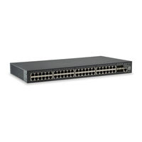
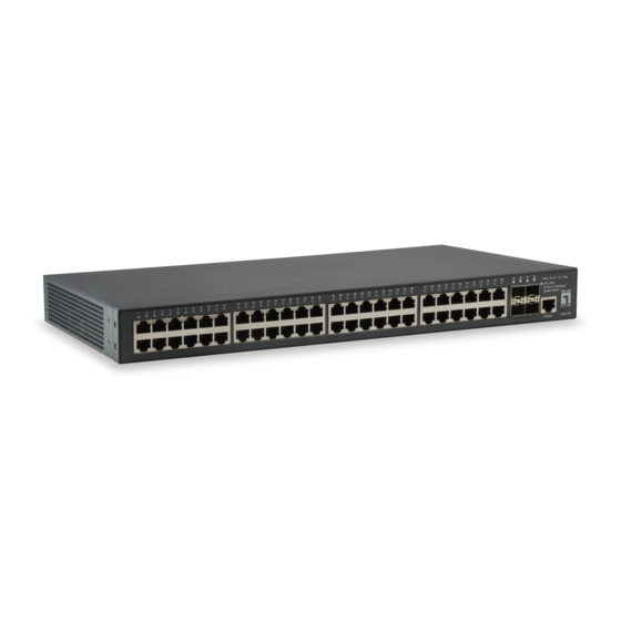
LevelOne GEL-5261 User Manual (570 pages)
52-Port L2 Managed Gigabit Switch
Brand:
LevelOne
| Category:
Switch
| Size: 15.04 MB
Table of Contents
User Manual
1
How to Use this Guide
3
Table of Contents
5
Contents
5
Figures
15
Tables
27
Getting Started
29
1 Introduction
31
Key Features
31
Table 1: Key Features
31
Description of Software Features
33
Address Resolution Protocol
37
System Defaults
38
Table 2: System Defaults
38
Web Configuration
41
2 Using the Web Interface
43
Connecting to the Web Interface
43
Navigating the Web Browser Interface
44
Dashboard
44
Figure 1: Dashboard
45
Configuration Options
46
Panel Display
46
Table 3: Web Page Configuration Buttons
46
Main Menu
47
Table 4: Switch Main Menu
47
3 Basic Management Tasks
63
Displaying System Information
64
Figure 2: System Information
64
Displaying Hardware/Software Versions
65
Configuring Support for Jumbo Frames
66
Figure 3: General Switch Information
66
Displaying Bridge Extension Capabilities
67
Figure 4: Configuring Support for Jumbo Frames
67
Figure 5: Displaying Bridge Extension Configuration
68
Managing System Files
69
Copying Files Via FTP/SFTP/TFTP or HTTP
69
Saving the Running Configuration to a Local File
71
Figure 6: Copy Firmware
71
Setting the Start-Up File
72
Figure 7: Saving the Running Configuration
72
Figure 8: Setting Start-Up Files
72
Showing System Files
73
Automatic Operation Code Upgrade
73
Figure 9: Displaying System Files
73
Setting the System Clock
77
Figure 10: Configuring Automatic Code Upgrade
77
Figure 11: Manually Setting the System Clock
78
Setting the Time Manually
78
Configuring NTP
79
Figure 12: Setting the Polling Interval for SNTP
79
Setting the SNTP Polling Interval
79
Configuring Time Servers
80
Figure 13: Configuring NTP
80
Figure 14: Specifying SNTP Time Servers
81
Figure 15: Adding an NTP Time Server
82
Figure 16: Showing the NTP Time Server List
82
Figure 17: Adding an NTP Authentication Key
83
Figure 18: Showing the NTP Authentication Key List
84
Setting the Time Zone
84
Configuring Summer Time
85
Figure 19: Setting the Time Zone
85
Table 5: Predefined Summer-Time Parameters
86
Configuring the Console Port
87
Figure 20: Configuring Summer Time
87
Figure 21: Console Port Settings
88
Configuring Telnet Settings
89
Displaying CPU Utilization
90
Figure 22: Telnet Connection Settings
90
Configuring CPU Guard
91
Figure 23: Displaying CPU Utilization
91
Displaying Memory Utilization
92
Figure 24: Configuring CPU Guard
92
Resetting the System
93
Figure 25: Displaying Memory Utilization
93
Figure 26: Restarting the Switch (Immediately)
95
Figure 27: Restarting the Switch (In)
95
Figure 28: Restarting the Switch (At)
96
Figure 29: Restarting the Switch (Regularly)
96
4 Interface Configuration
97
Port Configuration
98
Configuring by Port List
98
Configuring by Port Range
100
Figure 30: Configuring Connections by Port List
100
Displaying Connection Status
101
Figure 31: Configuring Connections by Port Range
101
Showing Port or Trunk Statistics
102
Figure 32: Displaying Port Information
102
Table 6: Port Statistics
102
Figure 33: Showing Port Statistics (Table)
105
Displaying Statistical History
106
Figure 34: Showing Port Statistics (Chart)
106
Figure 35: Configuring a History Sample
108
Figure 36: Showing Entries for History Sampling
108
Figure 37: Showing Status of Statistical History Sample
109
Figure 38: Showing Current Statistics for a History Sample
109
Displaying Transceiver Data
110
Figure 39: Showing Ingress Statistics for a History Sample
110
Configuring Transceiver Thresholds
111
Figure 40: Displaying Transceiver Data
111
Performing Cable Diagnostics
113
Figure 41: Configuring Transceiver Thresholds
113
Trunk Configuration
115
Figure 42: Performing Cable Tests
115
Configuring a Static Trunk
116
Figure 43: Configuring Static Trunks
116
Figure 44: Creating Static Trunks
117
Figure 45: Adding Static Trunks Members
118
Figure 46: Configuring Connection Parameters for a Static Trunk
118
Configuring a Dynamic Trunk
119
Figure 47: Showing Information for Static Trunks
119
Figure 48: Configuring Dynamic Trunks
119
Figure 49: Configuring the LACP Aggregator Admin Key
122
Figure 50: Enabling LACP on a Port
123
Figure 51: Configuring LACP Parameters on a Port
123
Figure 52: Showing Members of a Dynamic Trunk
124
Figure 53: Configuring Connection Settings for a Dynamic Trunk
124
Displaying LACP Port Counters
125
Figure 54: Showing Connection Parameters for Dynamic Trunks
125
Table 7: LACP Port Counters
125
Displaying LACP Settings and Status for the Local Side
126
Figure 55: Displaying LACP Port Counters
126
Table 8: LACP Internal Configuration Information
126
Figure 56: Displaying LACP Port Internal Information
127
Displaying LACP Settings and Status for the Remote Side
128
Table 9: LACP Remote Device Configuration Information
128
Configuring Load Balancing
129
Figure 57: Displaying LACP Port Remote Information
129
Figure 58: Configuring Load Balancing
130
Saving Power
131
Configuring Local Port Mirroring
132
Figure 59: Enabling Power Savings
132
Figure 60: Configuring Local Port Mirroring
132
Figure 61: Configuring Local Port Mirroring
133
Configuring Remote Port Mirroring
134
Figure 62: Displaying Local Port Mirror Sessions
134
Figure 63: Configuring Remote Port Mirroring
134
Figure 64: Configuring Remote Port Mirroring (Source)
137
Sampling Traffic Flows
138
Figure 65: Configuring Remote Port Mirroring (Intermediate)
138
Figure 66: Configuring Remote Port Mirroring (Destination)
138
Configuring Sflow Receiver Settings
139
Figure 67: Configuring an Sflow Receiver
140
Configuring an Sflow Polling Instance
141
Figure 68: Showing Sflow Receivers
141
Figure 69: Configuring an Sflow Instance
142
Figure 70: Showing Sflow Instances
142
Traffic Segmentation
143
Enabling Traffic Segmentation
143
Configuring Uplink and Downlink Ports
144
Figure 71: Enabling Traffic Segmentation
144
Table 10: Traffic Segmentation Forwarding
144
Figure 72: Configuring Members for Traffic Segmentation
145
Figure 73: Showing Traffic Segmentation Members
146
5 VLAN Configuration
147
IEEE 802.1Q Vlans
147
Figure 74: VLAN Compliant and VLAN Non-Compliant Devices
148
Configuring VLAN Groups
149
Figure 75: Creating Static Vlans
151
Figure 76: Modifying Settings for Static Vlans
151
Adding Static Members to Vlans
152
Figure 77: Showing Static Vlans
152
Figure 78: Configuring Static Members by VLAN Index
154
Figure 79: Configuring Static VLAN Members by Interface
155
IEEE 802.1Q Tunneling
156
Figure 80: Configuring Static VLAN Members by Interface Range
156
Figure 81: Qinq Operational Concept
157
Enabling Qinq Tunneling on the Switch
160
Creating CVLAN to SPVLAN Mapping Entries
161
Figure 82: Enabling Qinq Tunneling
161
Figure 83: Configuring CVLAN to SPVLAN Mapping Entries
162
Figure 84: Showing CVLAN to SPVLAN Mapping Entries
162
Adding an Interface to a Qinq Tunnel
163
Protocol Vlans
164
Figure 85: Adding an Interface to a Qinq Tunnel
164
Configuring Protocol VLAN Groups
165
Figure 86: Configuring Protocol Vlans
166
Figure 87: Displaying Protocol Vlans
166
Mapping Protocol Groups to Interfaces
166
Configuring MAC-Based Vlans
168
Figure 88: Assigning Interfaces to Protocol Vlans
168
Figure 89: Showing the Interface to Protocol Group Mapping
168
Figure 90: Configuring MAC-Based Vlans
170
Figure 91: Showing MAC-Based Vlans
170
6 Address Table Settings
171
Displaying the Dynamic Address Table
171
Clearing the Dynamic Address Table
172
Figure 92: Displaying the Dynamic MAC Address Table
172
Changing the Aging Time
173
Figure 93: Clearing Entries in the Dynamic MAC Address Table
173
Configuring MAC Address Learning
174
Figure 94: Setting the Address Aging Time
174
Figure 95: Configuring MAC Address Learning
175
Setting Static Addresses
176
Figure 96: Configuring Static MAC Addresses
177
Figure 97: Displaying Static MAC Addresses
177
Issuing MAC Address Traps
178
Figure 98: Issuing MAC Address Traps (Global Configuration)
178
Figure 99: Issuing MAC Address Traps (Interface Configuration)
179
7 Spanning Tree Algorithm
181
Overview
181
Figure 100: STP Root Ports and Designated Ports
182
Figure 101: MSTP Region, Internal Spanning Tree, Multiple Spanning Tree
182
Configuring Loopback Detection
183
Figure 102: Spanning Tree - Common Internal, Common, Internal
183
Configuring Global Settings for STA
185
Figure 103: Configuring Port Loopback Detection
185
Figure 104: Configuring Global Settings for STA (STP)
189
Figure 105: Configuring Global Settings for STA (RSTP)
189
Displaying Global Settings for STA
190
Figure 106: Configuring Global Settings for STA (MSTP)
190
Configuring Interface Settings for STA
191
Figure 107: Displaying Global Settings for STA
191
Table 11: Recommended STA Path Cost Range
192
Table 12: Default STA Path Costs
192
Figure 108: Determining the Root Port
193
Displaying Interface Settings for STA
196
Figure 109: Configuring Interface Settings for STA
196
Figure 110: STA Port Roles
197
Figure 111: Displaying Interface Settings for STA
198
Configuring Multiple Spanning Trees
199
Figure 112: Creating an MST Instance
200
Figure 113: Displaying MST Instances
200
Figure 114: Modifying the Priority for an MST Instance
201
Figure 115: Displaying Global Settings for an MST Instance
201
Figure 116: Adding a VLAN to an MST Instance
202
Figure 117: Displaying Members of an MST Instance
202
Configuring Interface Settings for MSTP
203
Figure 118: Configuring MSTP Interface Settings
204
Figure 119: Displaying MSTP Interface Settings
204
8 Congestion Control
205
Rate Limiting
205
Storm Control
206
Figure 120: Configuring Rate Limits
206
Figure 121: Configuring Storm Control
208
9 Class of Service
209
Layer 2 Queue Settings
209
Setting the Default Priority for Interfaces
209
Selecting the Queue Mode
210
Figure 122: Setting the Default Port Priority
210
Figure 123: Setting the Queue Mode (Strict)
212
Figure 124: Setting the Queue Mode (WRR)
212
Layer 3/4 Priority Settings
213
Figure 125: Setting the Queue Mode (Strict and WRR)
213
Setting Priority Processing to DSCP or Cos
214
Figure 126: Setting the Trust Mode
215
Mapping Cos Priorities to Per-Hop Behavior
215
Table 13: Default Mapping of Cos/Cfi Values to Queue/Cfi
215
Figure 127: Configuring Cos to Queue Mapping
216
Mapping DSCP Priorities to Per-Hop Behavior
216
Table 14: Default Mapping of DSCP Values to Queue/Cfi
217
Figure 128: Configuring DSCP to Queue Mapping
218
10 Quality of Service Overview
220
Configuring a Class Map
220
Figure 129: Configuring a Class Map
221
Figure 130: Showing Class Maps
222
Figure 131: Adding Rules to a Class Map
222
Creating Qos Policies
223
Figure 132: Showing the Rules for a Class Map
223
Figure 133: Configuring a Policy Map
225
Figure 134: Showing Policy Maps
225
Attaching a Policy Map to a Port
226
Figure 135: Adding Rules to a Policy Map
226
Figure 136: Showing the Rules for a Policy Map
226
Figure 137: Attaching a Policy Map to a Port
227
11 Voip Traffic Configuration Overview
230
Configuring Voip Traffic
230
Configuring Telephony OUI
231
Figure 138: Configuring a Voice VLAN
231
Configuring Voip Traffic Ports
232
Figure 139: Configuring an OUI Telephony List
232
Figure 140: Showing an OUI Telephony List
232
Figure 141: Configuring Port Settings for a Voice VLAN
234
12 Security Measures
235
AAA (Authentication, Authorization and Accounting)
236
Configuring Local/Remote Logon Authentication
237
Configuring Remote Logon Authentication Servers
238
Figure 142: Configuring the Authentication Sequence
238
Figure 143: Authentication Server Operation
238
Figure 144: Configuring Remote Authentication Server (RADIUS)
241
Figure 145: Configuring Remote Authentication Server (TACACS+)
242
Figure 146: Configuring AAA Server Groups
242
Configuring AAA Accounting
243
Figure 147: Showing AAA Server Groups
243
Figure 148: Configuring Global Settings for AAA Accounting
245
Figure 149: Configuring AAA Accounting Methods
246
Figure 150: Showing AAA Accounting Methods
247
Figure 151: Configuring AAA Accounting Service for 802.1X Service
247
Figure 152: Configuring AAA Accounting Service for Command Service
248
Figure 153: Configuring AAA Accounting Service for Exec Service
248
Configuring AAA Authorization
249
Figure 154: Displaying a Summary of Applied AAA Accounting Methods
249
Figure 155: Displaying Statistics for AAA Accounting Sessions
249
Figure 156: Configuring AAA Authorization Methods
251
Figure 157: Showing AAA Authorization Methods
251
Figure 158: Configuring AAA Authorization Methods for Exec Service
252
Figure 159: Displaying the Applied AAA Authorization Method
252
Configuring User Accounts
253
Figure 160: Configuring User Accounts
254
Web Authentication
255
Configuring Global Settings for Web Authentication
255
Figure 161: Showing User Accounts
255
Configuring Interface Settings for Web Authentication
256
Figure 162: Configuring Global Settings for Web Authentication
256
Network Access (MAC Address Authentication)
257
Figure 163: Configuring Interface Settings for Web Authentication
257
Table 15: Dynamic Qos Profiles
259
Configuring Global Settings for Network Access
260
Configuring Network Access for Ports
261
Figure 164: Configuring Global Settings for Network Access
261
Configuring a MAC Address Filter
263
Figure 165: Configuring Interface Settings for Network Access
263
Displaying Secure MAC Address Information
264
Figure 166: Configuring a MAC Address Filter for Network Access
264
Figure 167: Showing the MAC Address Filter Table for Network Access
264
Configuring HTTPS
266
Configuring Global Settings for HTTPS
266
Figure 168: Showing Addresses Authenticated for Network Access
266
Table 16: HTTPS System Support
267
Replacing the Default Secure-Site Certificate
268
Figure 169: Configuring HTTPS
268
Figure 170: Downloading the Secure-Site Certificate
269
Configuring the Secure Shell
270
Configuring the SSH Server
272
Generating the Host Key Pair
273
Figure 171: Configuring the SSH Server
273
Figure 172: Generating the SSH Host Key Pair
274
Importing User Public Keys
275
Figure 173: Showing the SSH Host Key Pair
275
Figure 174: Copying the SSH User's Public Key
276
Access Control Lists
277
Figure 175: Showing the SSH User's Public Key
277
Showing TCAM Utilization
278
Figure 176: Showing TCAM Utilization
280
Setting the ACL Name and Type
280
Figure 177: Creating an ACL
281
Configuring a Standard Ipv4 ACL
282
Figure 178: Showing a List of Acls
282
Configuring an Extended Ipv4 ACL
283
Figure 179: Configuring a Standard Ipv4 ACL
283
Configuring a Standard Ipv6 ACL
286
Figure 180: Configuring an Extended Ipv4 ACL
286
Configuring an Extended Ipv6 ACL
287
Figure 181: Configuring a Standard Ipv6 ACL
287
Figure 182: Configuring an Extended Ipv6 ACL
289
Configuring a MAC ACL
290
Figure 183: Configuring a MAC ACL
291
Configuring an ARP ACL
292
Binding a Port to an Access Control List
293
Figure 184: Configuring a ARP ACL
293
Figure 185: Binding a Port to an ACL
294
Showing ACL Hardware Counters
294
Figure 186: Showing ACL Statistics
295
Filtering IP Addresses for Management Access
296
Figure 187: Creating an IP Address Filter for Management Access
297
Figure 188: Showing IP Addresses Authorized for Management Access
297
Configuring Port Security
298
Configuring 802.1X Port Authentication
300
Figure 189: Configuring Port Security
300
Figure 190: Configuring Port Authentication
301
Configuring 802.1X Global Settings
302
Configuring Port Authenticator Settings for 802.1X
302
Figure 191: Configuring Global Settings for 802.1X Port Authentication
302
Displaying 802.1X Statistics
306
Figure 192: Configuring Interface Settings for 802.1X Port Authenticator
306
Table 17: 802.1X Statistics
306
Dos Protection
308
Figure 193: Showing Statistics for 802.1X Port Authenticator
308
DHCP Snooping
310
Figure 194: Protecting against Dos Attacks
310
DHCP Snooping Global Configuration
313
Figure 195: Configuring Global Settings for DHCP Snooping
314
DHCP Snooping VLAN Configuration
315
Figure 196: Configuring DHCP Snooping on a VLAN
315
Configuring Ports for DHCP Snooping
316
Displaying DHCP Snooping Binding Information
317
Figure 197: Configuring the Port Mode for DHCP Snooping
317
Ipv4 Source Guard
318
Configuring Ports for Ipv4 Source Guard
318
Figure 198: Displaying the Binding Table for DHCP Snooping
318
Configuring Static Bindings for Ipv4 Source Guard
320
Figure 199: Setting the Filter Type for Ipv4 Source Guard
320
Figure 200: Configuring Static Bindings for Ipv4 Source Guard
322
Displaying Information for Dynamic Ipv4 Source Guard Bindings
323
Figure 201: Displaying Static Bindings for Ipv4 Source Guard
323
ARP Inspection
324
Figure 202: Showing the Ipv4 Source Guard Binding Table
324
Configuring Global Settings for ARP Inspection
325
Configuring VLAN Settings for ARP Inspection
327
Figure 203: Configuring Global Settings for ARP Inspection
327
Figure 204: Configuring VLAN Settings for ARP Inspection
328
Configuring Interface Settings for ARP Inspection
329
Figure 205: Configuring Interface Settings for ARP Inspection
329
Displaying ARP Inspection Statistics
330
Table 18: ARP Inspection Statistics
330
Displaying the ARP Inspection Log
331
Figure 206: Displaying Statistics for ARP Inspection
331
Table 19: ARP Inspection Log
331
Figure 207: Displaying the ARP Inspection Log
332
13 Basic Administration Protocols
333
Configuring Event Logging
334
System Log Configuration
334
Table 20: Logging Levels
334
Figure 208: Configuring Settings for System Memory Logs
335
Remote Log Configuration
336
Figure 209: Showing Error Messages Logged to System Memory
336
Sending Simple Mail Transfer Protocol Alerts
337
Figure 210: Configuring Settings for Remote Logging of Error Messages
337
Figure 211: Configuring SMTP Alert Messages
338
Link Layer Discovery Protocol
339
Setting LLDP Timing Attributes
339
Configuring LLDP Interface Attributes
341
Figure 212: Configuring LLDP Timing Attributes
341
Configuring LLDP Interface CIVIC-Address
345
Figure 213: Configuring LLDP Interface Attributes
345
Table 21: LLDP MED Location CA Types
345
Figure 214: Configuring the CIVIC Address for an LLDP Interface
346
Displaying LLDP Local Device Information
347
Figure 215: Showing the CIVIC Address for an LLDP Interface
347
Table 22: Chassis ID Subtype
347
Table 23: System Capabilities
348
Table 24: Port ID Subtype
349
Figure 216: Displaying Local Device Information for LLDP (General)
350
Figure 217: Displaying Local Device Information for LLDP (Port)
350
Figure 218: Displaying Local Device Information for LLDP (Port Details)
350
Displaying LLDP Remote Device Information
351
Table 25: Remote Port Auto-Negotiation Advertised Capability
352
Figure 219: Displaying Remote Device Information for LLDP (Port)
357
Figure 220: Displaying Remote Device Information for LLDP (Port Details)
358
Displaying Device Statistics
359
Figure 221: Displaying Remote Device Information for LLDP (End Node)
359
Figure 222: Displaying LLDP Device Statistics (General)
361
Figure 223: Displaying LLDP Device Statistics (Port)
361
Simple Network Management Protocol
362
Table 26: Snmpv3 Security Models and Levels
363
Configuring Global Settings for SNMP
364
Figure 224: Configuring Global Settings for SNMP
364
Figure 225: Configuring the Local Engine ID for SNMP
365
Setting the Local Engine ID
365
Figure 226: Configuring a Remote Engine ID for SNMP
366
Specifying a Remote Engine ID
366
Figure 227: Showing Remote Engine Ids for SNMP
367
Setting Snmpv3 Views
367
Figure 228: Creating an SNMP View
368
Figure 229: Showing SNMP Views
368
Figure 230: Adding an OID Subtree to an SNMP View
369
Figure 231: Showing the OID Subtree Configured for SNMP Views
369
Configuring Snmpv3 Groups
370
Table 27: Supported Notification Messages
371
Figure 232: Creating an SNMP Group
374
Figure 233: Showing SNMP Groups
374
Figure 234: Setting Community Access Strings
375
Setting Community Access Strings
375
Configuring Local Snmpv3 Users
376
Figure 235: Showing Community Access Strings
376
Figure 236: Configuring Local Snmpv3 Users
378
Figure 237: Showing Local Snmpv3 Users
378
Configuring Remote Snmpv3 Users
379
Figure 238: Changing a Local Snmpv3 User Group
379
Figure 239: Configuring Remote Snmpv3 Users
381
Figure 240: Showing Remote Snmpv3 Users
381
Specifying Trap Managers
382
Figure 241: Configuring Trap Managers (Snmpv1)
385
Figure 242: Configuring Trap Managers (Snmpv2C)
385
Figure 243: Configuring Trap Managers (Snmpv3)
385
Creating SNMP Notification Logs
386
Figure 244: Showing Trap Managers
386
Figure 245: Creating SNMP Notification Logs
387
Figure 246: Showing SNMP Notification Logs
388
Showing SNMP Statistics
388
Figure 247: Showing SNMP Statistics
389
Remote Monitoring
390
Configuring RMON Alarms
390
Figure 248: Configuring an RMON Alarm
392
Figure 249: Showing Configured RMON Alarms
392
Configuring RMON Events
393
Figure 250: Configuring an RMON Event
394
Configuring RMON History Samples
395
Figure 251: Showing Configured RMON Events
395
Figure 252: Configuring an RMON History Sample
396
Figure 253: Showing Configured RMON History Samples
397
Figure 254: Showing Collected RMON History Samples
397
Configuring RMON Statistical Samples
398
Figure 255: Configuring an RMON Statistical Sample
399
Figure 256: Showing Configured RMON Statistical Samples
399
Switch Clustering
400
Figure 257: Showing Collected RMON Statistical Samples
400
Configuring General Settings for Clusters
401
Cluster Member Configuration
402
Figure 258: Configuring a Switch Cluster
402
Figure 259: Configuring a Cluster Members
403
Figure 260: Showing Cluster Members
403
Figure 261: Showing Cluster Candidates
404
Managing Cluster Members
404
Setting a Time Range
405
Figure 262: Managing a Cluster Member
405
Figure 263: Setting the Name of a Time Range
406
Figure 264: Showing a List of Time Ranges
406
Figure 265: Add a Rule to a Time Range
407
Figure 266: Showing the Rules Configured for a Time Range
407
Ethernet Ring Protection Switching
408
Figure 267: ERPS Ring Components
409
Figure 268: Ring Interconnection Architecture (Multi-Ring/Ladder Network)
410
ERPS Global Configuration
412
ERPS Ring Configuration
412
Figure 269: Setting ERPS Global Status
412
Figure 270: Sub-Ring with Virtual Channel
422
Figure 271: Sub-Ring Without Virtual Channel
422
Figure 272: Non-ERPS Device Protection
423
Figure 273: Creating an ERPS Ring
426
Figure 274: Creating an ERPS Ring
427
ERPS Forced and Manual Mode Operations
428
Figure 275: Showing Configured ERPS Rings
428
Table 28: ERPS Request/State Priority
429
LBD Configuration
432
Figure 276: Blocking an ERPS Ring Port
432
Configuring Global Settings for LBD
433
Figure 277: Configuring Global Settings for LBD
434
Configuring Interface Settings for LBD
435
Figure 278: Configuring Interface Settings for LBD
435
14 Multicast Filtering
437
Overview
437
Figure 279: Multicast Filtering Concept
437
Layer 2 IGMP (Snooping and Query for Ipv4)
438
Configuring IGMP Snooping and Query Parameters
440
Figure 280: Configuring General Settings for IGMP Snooping
443
Specifying Static Interfaces for a Multicast Router
444
Figure 281: Configuring a Static Interface for a Multicast Router
445
Figure 282: Showing Static Interfaces Attached a Multicast Router
445
Assigning Interfaces to Multicast Services
446
Figure 283: Showing Current Interfaces Attached a Multicast Router
446
Figure 284: Assigning an Interface to a Multicast Service
447
Setting IGMP Snooping Status Per Interface
448
Figure 285: Showing Static Interfaces Assigned to a Multicast Service
448
Figure 286: Configuring IGMP Snooping on a VLAN
453
Figure 287: Showing Interface Settings for IGMP Snooping
453
Filtering IGMP Query Packets and Multicast Data
454
Figure 288: Dropping IGMP Query or Multicast Data Packets
454
Displaying Multicast Groups Discovered by IGMP Snooping
455
Figure 289: Showing Multicast Groups Learned by IGMP Snooping
455
Displaying IGMP Snooping Statistics
456
Figure 290: Displaying IGMP Snooping Statistics - Query
458
Figure 291: Displaying IGMP Snooping Statistics - VLAN
459
Figure 292: Displaying IGMP Snooping Statistics - Port
459
Filtering and Throttling IGMP Groups
460
Enabling IGMP Filtering and Throttling
460
Configuring IGMP Filter Profiles
461
Figure 293: Enabling IGMP Filtering and Throttling
461
Figure 294: Creating an IGMP Filtering Profile
462
Figure 295: Showing the IGMP Filtering Profiles Created
462
Configuring IGMP Filtering and Throttling for Interfaces
463
Figure 296: Adding Multicast Groups to an IGMP Filtering Profile
463
Figure 297: Showing the Groups Assigned to an IGMP Filtering Profile
463
MLD Snooping (Snooping and Query for Ipv6)
465
Configuring MLD Snooping and Query Parameters
465
Figure 298: Configuring IGMP Filtering and Throttling Interface Settings
465
Setting Immediate Leave Status for MLD Snooping Per Interface
467
Figure 299: Configuring General Settings for MLD Snooping
467
Specifying Static Interfaces for an Ipv6 Multicast Router
468
Figure 300: Configuring Immediate Leave for MLD Snooping
468
Figure 301: Configuring a Static Interface for an Ipv6 Multicast Router
469
Figure 302: Showing Static Interfaces Attached an Ipv6 Multicast Router
469
Figure 303: Showing Current Interfaces Attached an Ipv6 Multicast Router
469
Assigning Interfaces to Ipv6 Multicast Services
470
Figure 304: Assigning an Interface to an Ipv6 Multicast Service
471
Figure 305: Showing Static Interfaces Assigned to an Ipv6 Multicast Service
471
Showing MLD Snooping Groups and Source List
472
Figure 306: Showing Current Interfaces Assigned to an Ipv6 Multicast Service
472
Displaying MLD Snooping Statistics
473
Figure 307: Showing Ipv6 Multicast Services and Corresponding Sources
473
Figure 308: Displaying MLD Snooping Statistics - Input
477
Figure 309: Displaying MLD Snooping Statistics - Output
477
Figure 310: Displaying MLD Snooping Statistics - Query
478
Figure 311: Displaying MLD Snooping Statistics - Summary (Port/Trunk)
479
Figure 312: Displaying MLD Snooping Statistics - Summary (VLAN)
480
Filtering and Throttling MLD Groups
481
Figure 313: Clearing MLD Snooping Statistics
481
Configuring MLD Filter Profiles
482
Enabling MLD Filtering and Throttling
482
Figure 314: Enabling MLD Filtering and Throttling
482
Figure 315: Creating an MLD Filtering Profile
483
Figure 316: Showing the MLD Filtering Profiles Created
484
Figure 317: Adding Multicast Groups to an MLD Filtering Profile
484
Configuring MLD Filtering and Throttling for Interfaces
485
Figure 318: Showing the Groups Assigned to an MLD Filtering Profile
485
Filtering MLD Query Packets on an Interface
486
Figure 319: Configuring MLD Filtering and Throttling Interface Settings
486
Figure 320: Dropping MLD Query Packets
487
15 IP Tools
489
Using the Ping Function
489
Figure 321: Pinging a Network Device
490
Using the Trace Route Function
491
Address Resolution Protocol
492
Figure 322: Tracing the Route to a Network Device
492
Table 29: Address Resolution Protocol
492
Basic ARP Configuration
493
Figure 323: Proxy ARP
493
Configuring Static ARP Addresses
494
Figure 324: Configuring General Settings for ARP
494
Figure 325: Configuring Static ARP Entries
495
Displaying Dynamic or Local ARP Entries
496
Figure 326: Displaying Static ARP Entries
496
Figure 327: Displaying ARP Entries
496
Displaying ARP Statistics
497
Figure 328: Displaying ARP Statistics
497
Table 30: ARP Statistics
497
16 IP Configuration
499
Setting the Switch's IP Address (IP Version 4)
499
Configuring Ipv4 Interface Settings
499
Figure 329: Configuring a Static Ipv4 Address
501
Figure 330: Configuring a Dynamic Ipv4 Address
502
Setting the Switch's IP Address (IP Version 6)
503
Configuring the Ipv6 Default Gateway
503
Figure 331: Showing the Configured Ipv4 Address for an Interface
503
Configuring Ipv6 Interface Settings
504
Figure 332: Configuring the Ipv6 Default Gateway
504
Figure 333: Configuring General Settings for an Ipv6 Interface
508
Configuring an Ipv6 Address
509
Showing Ipv6 Addresses
511
Figure 334: Configuring an Ipv6 Address
511
Figure 335: Showing Configured Ipv6 Addresses
512
Showing the Ipv6 Neighbor Cache
513
Table 31: Show Ipv6 Neighbors - Display Description
513
Showing Ipv6 Statistics
514
Figure 336: Showing Ipv6 Neighbors
514
Table 32: Show Ipv6 Statistics - Display Description
515
Figure 337: Showing Ipv6 Statistics (Ipv6)
520
Figure 338: Showing Ipv6 Statistics (Icmpv6)
521
Figure 339: Showing Ipv6 Statistics (UDP)
521
Showing the MTU for Responding Destinations
522
Figure 340: Showing Reported MTU Values
522
Table 33: Show MTU - Display Description
522
17 General IP Routing
523
Overview
523
Initial Configuration
523
Routing Path Management
523
IP Routing and Switching
524
Figure 341: Virtual Interfaces and Layer 3 Routing
524
Routing Protocols
525
Displaying the Routing Table
525
Configuring Static Routes
526
Figure 342: Configuring Static Routes
527
Figure 343: Displaying Static Routes
527
Figure 344: Displaying the Routing Table
528
18 IP Services
529
Domain Name Service
529
Configuring General DNS Service Parameters
529
Configuring a List of Domain Names
530
Configuring a List of Name Servers
530
Figure 345: Configuring General Settings for DNS
530
Figure 346: Configuring a List of Domain Names for DNS
531
Figure 347: Showing the List of Domain Names for DNS
531
Figure 348: Configuring a List of Name Servers for DNS
532
Configuring Static DNS Host to Address Entries
533
Multicast Domain Name Service
533
Figure 349: Showing the List of Name Servers for DNS
533
Displaying the DNS Cache
534
Figure 350: Configuring Static Entries in the DNS Table
534
Figure 351: Showing Static Entries in the DNS Table
534
Figure 352: Showing Entries in the DNS Cache
535
Dynamic Host Configuration Protocol
536
Configuring DHCP Relay Service
536
Figure 353: Configuring Multicast DNS
536
Specifying a DHCP Client Identifier
537
Table 34: Options 60, 66 and 67 Statements
537
Table 35: Options 55 and 124 Statements
537
Enabling DHCP Dynamic Provision
538
Figure 354: Specifying a DHCP Client Identifier
538
Figure 355: Layer 3 DHCP Relay Service
538
Figure 356: Configuring DHCP Relay Service
539
Figure 357: Enabling Dynamic Provisioning Via DHCP
540
Appendices
541
A Software Specifications
541
Software Features
543
Management Features
544
Standards
545
Management Information Bases
545
Troubleshooting
547
Problems Accessing the Management Interface
547
Table 36: Troubleshooting Chart
547
Using System Logs
548
License Information
549
The GNU General Public License
549
Ip Multicast Filtering
556
Advertisement
Advertisement
Related Products
LevelOne GEL-5271-v1
LevelOne GEL-5271
LevelOne GEL-2870
LevelOne GEL-1061
LevelOne GEL-2861
LevelOne GEL-2460
LevelOne GEL-2670 24 GE + 2 GE SFP
LevelOne GEL-2060
LevelOne GEL-1051
LevelOne GEL-2871-v1
LevelOne Categories
Switch
Network Router
Security Camera
Adapter
Wireless Access Point
More LevelOne Manuals
Login
Sign In
OR
Sign in with Facebook
Sign in with Google
Upload manual
Upload from disk
Upload from URL