Sign In
Upload
Manuals
Brands
Leuze electronic Manuals
Measuring Instruments
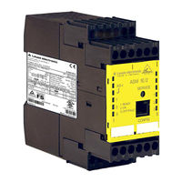
ASM1E-m/1
Leuze electronic ASM1E-m/1 Manuals
Manuals and User Guides for Leuze electronic ASM1E-m/1. We have
1
Leuze electronic ASM1E-m/1 manual available for free PDF download: Manual
Leuze electronic ASM1E-m/1 Manual (86 pages)
Brand:
Leuze electronic
| Category:
Measuring Instruments
| Size: 4 MB
Table of Contents
Table of Contents
3
General Information
7
Explanation of Symbols
7
Declaration of Conformity
7
Standards
7
Definition of Terms
8
Abbreviations
10
Brief Description
11
Figure 1.1:Safe and Standard Components in an AS-I Network
11
Figure 1.2:Example - Monitoring of 2 Decentral AS-I Actuator Groups
12
Figure 1.3:Example - Monitoring of 2 Decentral AS-I Actuator Groups
13
Different Types of AS-I Safety Monitors
15
Safety
19
Approved Purpose and Foreseeable Improper Operation
19
Proper Use
19
Foreseeable Misuse
21
Competent Personnel
21
Responsibility for Safety
22
Exemption of Liability
22
Residual Risks (en ISO 12100-1)
22
Areas of Application
23
Additional Safety Notices for the "Muting" Special Function
23
Safety Notices for Muting Applications
23
Organizational Measures
26
Muting Via AS-I
27
Optoelectronic Protective Devices for Muting Applications
27
Figure 3.1: Variants of the Optoelectronic Protective Device for Muting Applications
27
Usage Examples
28
4-Sensor Sequential Muting
28
Figure 3.2: 4-Sensor Sequential-Muting Application at a Robot Station
28
2-Sensor Parallel Muting
29
System Design and Muting Modes
29
System Design
29
Figure 3.3: 2-Sensor Parallel Muting Application at a Palletizer System
29
Figure 3.4: Principle System Design for Muting Via AS-I, 2-Sensor Parallel Muting
30
4-Sensor Sequential Muting
32
Figure 3.5: System Arrangement for 4-Sensor Sequential Muting
33
Figure 3.6: Time Diagram: 4-Sensor Sequential Muting
34
2-Sensor Parallel Muting
35
Figure 3.7: System Arrangement for 2-Sensor Parallel Muting
35
Figure 3.8: Time Diagram: 2-Sensor Parallel Muting
36
Muting Time Limit - Muting Timeout
37
Muting Restart - Override Mode
37
Muting Status
39
Mounting the Muting System Components
40
Figure 3.9: Arrangement of the Muting Sensors, 4-Sensor Sequential Muting
41
Figure 3.10: Arrangement of Muting Sensors MS2 and MS3
41
Figure 3.11:Arrangement of the Muting Sensors, 2-Sensor Parallel Muting
42
Specifications
43
General Technical Data
43
Safety-Relevant Characteristic Data
45
Figure 4.1: Example 1 - Calculation of the System Reaction Time
46
Figure 4.2: Example 2 - Calculation of the System Reaction Time
47
Figure 4.3: Example 3 - Calculation of the System Reaction Time
47
Dimensioned Drawings
48
Scope of Delivery
48
Figure 4.4: Dimensions
48
Mounting
49
Mounting in the Switching Cabinet
49
Figure 5.1: Mounting
49
Figure 5.2: Removable Connection Terminals
50
Figure 5.3: Removing and Mounting Encoded Connection Terminals
50
Figure 5.4: Mounting Accessories for Sealing the Device
51
Electrical Connection ASM1/1, ASM1E/1 and ASM1E-M/1
52
Terminal Assignment
52
Figure 6.1: Terminal Arrangement / Block Diagram of AS-I Safety Monitor ASM1/1
52
Connection Overview
54
Figure 6.2: Connection Overview of AS-I Safety Monitor ASM1/1, ASM1E/1
54
Electrical Connection ASM1/2, ASM1E/2 and ASM1E-M/2
55
Terminal Assignment
55
Figure 7.1: Terminal Arrangement / Block Diagram of AS-I Safety Monitor ASM1/2
55
Connection Overview
57
Figure 7.2: Connection Overview of AS-I Safety Monitor ASM1/2, ASM1E/2 and
57
Electrical Connection ASM2E/1, ASM2E/2, ASM2E-M/1 and ASM2E-M/2
58
Terminal Assignment
58
Figure 8.1: Terminal Arrangement / Block Diagram of AS-I Safety Monitor ASM2E/1, ASM2E/2
58
Connection Overview
60
Figure 8.2: Connection Overview of AS-I Safety Monitor ASM2E/1, ASM2E/2, ASM2E
60
Connection for Actuator Monitoring
61
Figure 8.3: Connection of the Terminals of the Safe AS-I Output for Actuator Monitoring
61
Connection for Coupling to Another AS-I Network
62
Figure 8.4: Connection of the Terminals of the Safe AS-I Output for Network Coupling
62
Electrical Connection of All Types
63
AS-I Bus Connection
63
Figure 9.1: AS-I Cable Variants
63
Serial Interface
64
Figure 9.2: Location of the RS 232C Configuration Interface
64
Function and Commissioning
65
Function and Operating Modes
65
Start-Up Operation
65
Configuration Operation
66
Protective Operation
66
Display and Operating Elements
67
Figure 10.1: Overview of Device Leds
67
Switching on the Device
68
Device Configuration and Parameterisation
68
Technical Safety Documentation for the Application
69
Maintenance
70
Checking for Safe Shutdown
70
Status Display, Errors and Error Rectification
71
Status Display on the Device / Error Diagnosis on the PC
71
Troubleshooting Tips
71
Error Release with the "Service" Button
71
Replacing Defective Safe AS-I Slaves
72
Replacing a Defective Safe AS-I Slave
72
Replacing Several Defective Safe AS-I Slaves
72
Replacing a Defective AS-I Safety Monitor
74
What to Do if You Forget the Password
75
Diagnostics Via AS-I
76
General Procedure
76
Telegrams
77
Diagnosis of AS-I Safety Monitor
77
Diagnosis of Devices, Sorted According to OSSD
81
Diagnosis of Devices, Unsorted
83
Example: Querying with Diagnosis Sorted According to OSSD
85
Figure 13.1: Querying with Diagnosis Sorted According to Output Circuit
85
Advertisement
Advertisement
Related Products
Leuze electronic ASM1 Series
Leuze electronic ASM2E Series
Leuze electronic ASM1/1
Leuze electronic ASM1E Series
Leuze electronic ASM1E/1
Leuze electronic ASM1/2
Leuze electronic ASM1E/2
Leuze electronic ASM2/1
Leuze electronic ASM2E/2
Leuze electronic AMS 308i 40 H
Leuze electronic Categories
Accessories
Barcode Reader
Measuring Instruments
Security Sensors
Scanner
More Leuze electronic Manuals
Login
Sign In
OR
Sign in with Facebook
Sign in with Google
Upload manual
Upload from disk
Upload from URL