Sign In
Upload
Manuals
Brands
Leuze Manuals
Security Sensors
CML 730-PS
Leuze CML 730-PS Manuals
Manuals and User Guides for Leuze CML 730-PS. We have
1
Leuze CML 730-PS manual available for free PDF download: Operating Instructions Manual
Leuze CML 730-PS Operating Instructions Manual (132 pages)
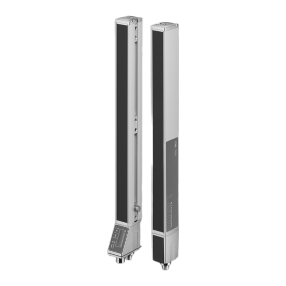
Measuring light curtain
Brand:
Leuze
| Category:
Security Sensors
| Size: 11 MB
Table of Contents
Table of Contents
3
1 About this Document
7
Used Symbols and Signal Words
7
Terms and Abbreviations
7
2 Safety
9
Intended Use
9
Foreseeable Misuse
9
Competent Persons
9
Exemption of Liability
10
3 Device Description
11
General Information
11
General Performance Characteristics
11
Connection Technology
12
Display Elements
12
Operation Indicators on the Receiver Control Panel
12
Display on the Receiver Control Panel
13
Operating Indicators on the Transmitter
14
Operating Elements on the Receiver Control Panel
14
Menu Structure of the Receiver Control Panel
14
Menu Navigation on the Receiver Control Panel
17
Meaning of the Display Icons
17
Level Display
17
Menu Navigation
18
Editing Value Parameters
18
Editing Selection Parameters
19
4 Functions
21
Beam Modes
21
Parallel
21
Diagonal
21
Crossed-Beam
22
Measurement Beam Sequence
23
Beam-Stream
24
Evaluation Functions
24
Hold Function
25
Blanking
25
Power-Up Teach
27
Smoothing
27
Cascading/Triggering
29
External Triggering
31
Internal Triggering
31
Block Evaluation of Beam Areas
32
1Defining Beam Area
33
2Autosplitting
33
3Mapping Beam Area to Switching Output
33
4Teach Height Area
34
Switching Outputs
36
1Light/Dark Switching
36
2Time Functions
36
Interference Suppression (Filter Depth)
36
Power Setting
37
Validation Output
38
Key Lock
38
5 Applications
40
Height Measurement
40
Object Measurement
41
Width Measurement, Orientation Detection
42
Contour Measurement
43
Gap Control/Gap Measurement
44
Hole Recognition
45
Power Setting
45
6 Mounting and Installation
46
Mounting the Light Curtain
46
Definition of Directions of Movement
47
Fastening Via Sliding Blocks
48
Fastening Via Swivel Mount
48
Fastening Via Swiveling Mounting Brackets
49
7 Electrical Connection
50
Shielding and Line Lengths
50
Shielding
50
Cable Lengths for Shielded Cables
52
Connection and Interconnection Cables
53
Device Connections
53
Digital Inputs/Outputs on Connection X1
53
Electrical Connection - CML 700I with IO-Link/Analog Interface
53
X1 Pin Assignment - CML 700I with Analog Interface
54
X2/X3 Pin Assignment - CML 700I with IO-Link/Analog Interface
55
Electrical Supply
56
8 Starting up the Device - Basic Configuration
57
Aligning Transmitter and Receiver
57
Teaching the Environmental Conditions
59
Teach Via Receiver Control Panel
59
Teaching Via a Control Signal from the Control
61
Check Alignment
62
Setting the Function Reserve
62
Extended Configurations on the Receiver Control Panel Menu
65
Define Digital Inputs/Outputs
65
Inversion of the Switching Behavior (Light/Dark Switching)
67
Defining the Filter Depth
68
Defining the Display Properties
68
Changing the Language
69
Product Information
69
Reset to Factory Settings
70
9 Starting up the Device - Analog Output
71
Analog Output Configuration on the Receiver Control Panel
71
Analog Output Configuration Via the Sensor Studio Configuration Software
71
Behavior of the Analog Output
72
10 Starting up the Device - IO-Link Interface
74
Defining IO-Link Device Configurations on the Receiver Control Panel
74
Defining Configurations Via the IO-Link Master Module of the PLC-Specific Software
74
Parameter/Process Data for IO-Link
75
11 Example Configurations
88
Example Configuration - Reading out 64 Beams (Beam-Stream)
88
1Configuration of Beam-Stream Process Data Via IO-Link Interface
88
Example Configuration - Mapping of Beams 1
88
1Configuration of Area/Output Mapping (General)
88
2Configuration of an Area/Output Mapping Via IO-Link Interface
89
Example Configuration - Hole Recognition
89
1Configuration of Hole Recognition Via IO-Link Interface
90
Example Configuration - Activating and Deactivating Blanking Areas
90
1Configuration of Blanking Areas (General)
90
2Configuration of Blanking Areas Via IO-Link Interface
90
Example Configuration - Smoothing
91
1Smoothing Configuration (General)
91
2Configuration of Smoothing Via IO-Link Interface
91
Example Configuration - Cascading
91
1Configuration of a Cascading Arrangement (General)
91
2Configuration of a Cascading Arrangement Via IO-Link Interface
94
Example Configuration - Detecting Transparent Films
95
Example Configuration - Reliable Beam Penetration through Opaque Films
96
Example Configuration - Double Film Detection
97
12 Connecting to a PC - Sensor Studio
98
System Requirements
98
Installing Sensor Studio Configuration Software and IO-Link USB Master
99
1Installing the Sensor Studio FDT Frame
99
2Installing Drivers for IO-Link USB Master
99
3Connecting IO-Link USB Master to the PC
99
4Connect the IO-Link USB Master to the Light Curtain
100
5Installing the DTM and IODD
101
Starting the Sensor Studio Configuration Software
101
Short Description of the Sensor Studio Configuration Software
103
1FDT Frame Menu
104
Identification Configuration Process Diagnostics
104
CONFIGURATION Function
104
PROCESS Function
105
DIAGNOSTICS Function
105
Exiting Sensor Studio
105
13 Troubleshooting
107
What to Do in Case of Failure
107
Operating Indicators of the Leds
107
Error Codes in the Display
108
14 Care, Maintenance and Disposal
112
Cleaning
112
Servicing
112
1Firmware Update
112
Disposing
112
15 Service and Support
113
16 Technical Data
114
General Specifications
114
Timing
116
Minimum Object Diameter for Stationary Objects
118
Dimensioned Drawings
119
Dimensioned Drawings: Accessories
120
17 Ordering Information and Accessories
124
Nomenclature
124
Accessories - CML 700I with IO-Link/Analog Interface
125
1IO-Link Analog Interface (Connection in the Switch Cabinet: Screw Terminals)
126
2IO-Link Interface (Connection to IO-Link Master)
128
Accessories - Fastening Technology
129
Accessories - PC Connection
130
Accessories - Device Columns
130
Scope of Delivery
130
18 EC Declaration of Conformity
132
Advertisement
Advertisement
Related Products
Leuze CML730i-T05-160.A-M12
Leuze CML730i-T05-800.A-M12
Leuze CML730i-T10-1920.A-M12
Leuze CML730i-T05-1040.A-M12
Leuze CML730i-T10-1920.R-M12
Leuze CML730i-T05-400.A-M12
Leuze CML730i-T05-240.A-M12
Leuze CML 720i
Leuze CMS 748i
Leuze CMS 708i
Leuze Categories
Barcode Reader
Accessories
Measuring Instruments
Security Sensors
Safety Equipment
More Leuze Manuals
Login
Sign In
OR
Sign in with Facebook
Sign in with Google
Upload manual
Upload from disk
Upload from URL