Sign In
Upload
Manuals
Brands
LEM Manuals
Measuring Instruments
DCBM 400 Series
LEM DCBM 400 Series Manuals
Manuals and User Guides for LEM DCBM 400 Series. We have
1
LEM DCBM 400 Series manual available for free PDF download: Operation Manual
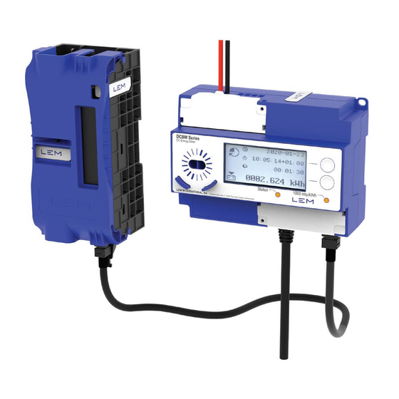
LEM DCBM 400 Series Operation Manual (95 pages)
DC Energy Meter
Brand:
LEM
| Category:
Measuring Instruments
| Size: 13 MB
Table of Contents
Table of Contents
2
Safety Rules
10
Safety Warning
10
Important Notices
11
Symbols and Conventions
11
Document Information
12
Document Overview
12
Figure 1. Documentation Information Versus Associated Publics
12
Figure 2. Documentation Set for DCBM 400/600 Product Family
12
Document Issue
13
Company Details
13
Revision History
13
Related Documents
13
Abbreviations
14
Disclaimer
15
Intellectual Property Rights
15
Third Party Licensing
15
Warranty
16
Product Introduction
17
LEM and the DCBM
17
DCBM in EV Charging Systems
18
Figure 3. Namings Designating Equipment and Protagonists
18
Figure 4. Product Construction
19
DCBM 400/600 in EVSE
21
DCBM in 50 Kw EVSE
21
Figure 5. Typical 50 Kw Architecture
21
DCBM in 350 Kw EVSE
22
Figure 6. DCBM in a Typical 50 Kw EVSE
22
Figure 7. Typical 350 Kw EVSE System
22
Figure 8. DCBM in a Typical 350 Kw EVSE
23
Certification and Compliance
24
Standards
24
Certification
24
Product Designation
24
Figure 9. Simplified List of References for 400 a Current Rating
24
Figure 10. Simplified List of References for 600 a Current Rating
24
Figure 11. Full List of References for the DCBM 400/600 Product Family
25
Device Description and Mechanical Integration
26
Package Content
26
Meter Unit Description
27
Sensor Unit Description
27
Mounting and Unmounting
27
Meter Unit
27
Mounting
27
Unmounting
28
Sensor Unit
28
Product Dimensions
29
Meter Unit
29
Figure 12. Meter Unit Dimensions
29
Figure 13. Meter Unit Aperture for Electrical Cabinet
29
Sensor Unit
30
Figure 14. Sensor Unit Dimensions
30
Connection
31
Figure 15. DCBM Connection
31
Figure 16. Connection and Wiring Diagrams
32
Table 1. Ports Definition
32
Figure 17. Sensor Unit Integration
33
Table 2. Torque Values for Installation
33
Table 3. Bus Bar Drilling
33
Cable Management
34
Sealing
34
Manufacturer Seals
34
Installation Seals
34
Figure 18. Cable Management
34
Figure 19. Manufacturer Seals
34
Disposing
35
Marking
36
Electrical Functions
37
Safety Features
37
Integration Solutions
37
Overview
37
Counting Direction
37
Table 4. Counting Direction References
37
Voltage Side
38
Figure 20. Import and Export Energy Registers Matched with Energy Flow
38
Direct Counting Direction Connection Requirements
39
Figure 21. Connection for Direct Counting Direction References (Dcbm_Nxd_X000_0000)
39
Reverse Counting Direction Connection Requirements
40
Figure 22. Connection for Reverse Counting Direction References (Dcbm_Nxd_X010_0000)
40
Energy Registering
41
Figure 23. Counting Quadrants for the DCBM
41
Handling Energy Losses
42
Cable Loss Compensation
42
Principle
42
Figure 24. Example of Energy Losses in an EVSE Electrical Circuit
42
Figure 25. Current Accuracy Graphs with and Without Cable Loss Compensation
43
Compensation Mechanism
44
Figure 26. Integration Examples Using Cable Loss Compensation
44
Setting the Compensation Level
45
Setting Cableid Value
45
Figure 27. Distribution of RP
45
Four-Wire Measurement
46
Figure 28. Integration Example for Four-Wire Measurement
46
Performances
47
General
47
Accuracy
48
Insulation
48
Operating Conditions
49
Sensor Unit
49
Meter Unit
49
Data Link Cable
49
Display and Navigation
50
Quick Start
50
STEP 1 - Power up the DCBM
50
Figure 29. Sequence of Screens on Boot and During Idle
50
STEP 2 - Check Transaction Data
51
Figure 30. Sequence of Screens for Beginning of Transactions
51
Figure 31. Sequences of Screens for End of Transactions
51
STEP 3 - Achieve Further Validation
52
Figure 32. Maintenance Screens Which Can Help Metrological Validation
52
General Display Concepts
53
Figure 33. Global State Machine of the Display
53
Figure 34. Identification of Buttons
53
Figure 35. Visual Distinction for Legal Relevance on the Display
53
Boot Screens
54
Overview
54
Effect of Buttons
54
Idle Screen
55
Overview
55
Available Data
55
Effect of Buttons
55
Transactions Screens
55
Layout of Screens
55
Figure 36. Transaction Screens Layout
55
State Symbols
56
Transaction Energy Register
56
Figure 37. State Machine for Transaction Screens
56
Figure 38. Transaction Energy Register
56
Rolling Data
57
Effect of Buttons
58
Maintenance State
59
Overview
59
Layout of Screens
59
Effect of Buttons
59
Figure 39. Maintenance Screens Layout
59
Available Data
60
STATUS Category
60
LIVE MEASURE Category
61
DEVICE Category
62
FIRMWARE Category
63
CLOCK Category
64
Error Screen
65
Index of Symbols in Screens
66
Transaction-Specific
66
Metrology
67
Time Management
68
Other Data
68
Software Concepts
69
Interfaces
69
Table 5. REST API Access and Associated HTTP Methods
69
Transactions
70
Concept
70
Figure 40. Transaction Concept
70
Conditions to Start and Input Parameters
71
Figure 41. Example of Body for Start Request
71
Table 6. Transaction Preconditions in Device Implementation
71
Table 7. Required Inputs to a New Transaction
71
Transaction Readouts
72
Table 8. Solutions for Retrieving Past Transactions
72
Memory Depth
73
Required Action Following a Transaction
73
Fallback Procedure for Unavailable Upload
73
Measurements
74
Energy Registering
74
Bidirectional Current Flow
74
Total Energy Registers
74
Table 9. Measurement Results, Metrologically Relevant
74
Transaction Energy Registers
75
Other Measurements
75
Figure 42. "Transaction" Vs "Total" Energy Registers (Import or Export)
75
Data Authenticity
76
Overview
76
Keys Specifics
76
Figure 43. Keys Specifics for Signature Checks
76
Table 10. Solutions for Signatures Verification
76
Status and Errors Flags
77
Overview
77
Status/Errors Value Field Description
77
Figure 44. Description of the 2 Formats of Status and Errors
77
Current Status
78
Figure 45. Illustration of Using Value Field, Example for Status Register
78
Figure 46. Status Field Persistence
78
Figure 47. Specific Reversedvoltage Status Persistence
79
Table 11. List of Status Flags
79
Transactionstatus Field
80
Figure 48. Transaction Status Field Persistence
80
Errors
81
Table 12. List of Error Flags
81
OCMF Error and Status Fields
82
Table 13. OCMF EF Field Equivalents
82
Table 14. OCMF ST Field Equivalents
82
Event Logbook
83
Connectivity Settings
84
IP Addressing
84
Static Addressing
84
Dhcp
84
Dns
85
Http & Tls
85
Https
85
HTTP Port
85
Time Management
86
Time Synchronization
86
Overview
86
General Constraints
86
Synchronization Solutions
86
Command Time Synchronization
87
NTP Synchronization
87
Local Time
88
Time Zone
88
Daylight Saving Time
88
Troubleshooting
89
Wrong Statuses
89
Raised Errors
91
Other Software Issues
93
Appendix - PTB Type-Examination Certificate for DCBM
94
Advertisement
Advertisement
Related Products
LEM DCBM Series
LEM DCBM_SU40 Series
LEM DCBM_SU60 Series
LEM DCBM 600 Series
LEM DCBM 100 Series
LEM d400
LEM DX 26 PLUS
LEM DX 24
LEM DVL 1500/SP8
LEM ANALYST 2060
LEM Categories
Kitchen Appliances
Transducer
Speaker System
Meat Grinder
Amplifier
More LEM Manuals
Login
Sign In
OR
Sign in with Facebook
Sign in with Google
Upload manual
Upload from disk
Upload from URL