Sign In
Upload
Manuals
Brands
Lantronix Manuals
Server
EDS2100
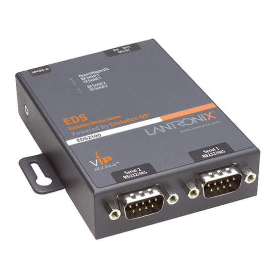
Lantronix EDS2100 Manuals
Manuals and User Guides for Lantronix EDS2100. We have
4
Lantronix EDS2100 manuals available for free PDF download: Command Reference Manual, User Manual, Quick Start Manual
Lantronix EDS2100 User Manual (149 pages)
Device Server
Brand:
Lantronix
| Category:
Server
| Size: 4 MB
Table of Contents
Intellectual Property
2
Warranty
2
Contacts
2
Disclaimer
2
Revision History
3
Table of Contents
4
List of Figures
9
List of Tables
12
1: about this Guide
14
Chapter and Appendix Summaries
14
Additional Documentation
15
2: Introduction
16
Key Features
16
Protocol Support
17
Evolution OS™ Application
17
Additional Features
18
Modem Emulation
18
Web-Based Configuration and Troubleshooting
18
Command-Line Interface (CLI)
18
SNMP Management
18
XML-Based Architecture and Device Control
18
Really Simple Syndication (RSS)
18
Enterprise-Grade Security
18
Terminal Server/Device Management
19
Troubleshooting Capabilities
19
Configuration Methods
19
Addresses and Port Numbers
20
Hardware Address
20
IP Address
20
Port Numbers
20
Figure 2-1 Sample Hardware Address
20
Product Information Label
21
Figure 2-2 Product Label
21
3: Installation of EDS1100
22
Package Contents
22
User-Supplied Items
22
Hardware Components
23
Figure 3-1 EDS1100 DB25 (Female) Serial Port
23
Figure 3-2 EDS1100 RS-232 Pinouts
23
Figure 3-3 EDS1100 RS-422 (4-Wire) Pinouts
23
Back Panel
24
Reset Button
24
Figure 3-4 EDS1100 RS-485 (2-Wire) Pinouts
24
Figure 3-5 EDS1100 Back Panel
24
Top Leds
25
Installing the EDS1100
25
Figure 3-6 EDS1100 Top Leds
25
Table 3-7 EDS1100 Leds and Descriptions
25
Figure 3-8 EDS1100 Connections
26
4: Installation of EDS2100
27
Package Contents
27
User-Supplied Items
27
Hardware Components
28
Figure 4-1 EDS2100 Male DB9 DTE Serial Ports
28
Figure 4-2 EDS2100 Pinout Configuration for RS-232
28
Figure 4-3 EDS2100 Pinout Configuration for RS-422 (4-Wire)
28
Back Panel
29
Reset Button
29
Figure 4-4 EDS2100 Pinout Configuration for RS-485 (2-Wire)
29
Figure 4-5 EDS2100 Ethernet RJ45 Port, Reset Button, and Power Plug
29
Top Leds
30
Figure 4-6 EDS2100 Top Leds
30
Table 4-7 EDS2100 Leds and Descriptions
30
Installing the EDS2100
31
Figure 4-8 EDS2100 Connections
32
5: Using Deviceinstaller
33
Installing Deviceinstaller
33
Accessing the EDS1100/2100 Unit Using Deviceinstaller
33
Table 5-1 Device Details Summary
33
6: Configuration Using Web Manager
35
Accessing Web Manager
35
Figure 6-1 Prompt for User Name and Password
35
Device Status Page
36
Figure 6-2 Web Manager Home Page
36
Web Manager Page Components
37
Figure 6-3 Components of the Web Manager Page
37
Navigating the Web Manager
38
Table 6-4 Summary of Web Manager Pages
38
7: Network Settings
40
Network 1 (Eth0) Interface Status
40
Figure 7-1 Network 1 (Eth0) Interface Status
40
Network 1 (Eth0) Interface Configuration
41
Figure 7-2 Network 1 (Eth0) Interface Configuration
41
Table 7-3 Network 1 (Eth0) Interface Configuration
41
Network 1 Ethernet Link
43
Figure 7-4 Network 1 Ethernet Link
43
Table 7-5 Network 1 Ethernet Link
43
8: Line and Tunnel Settings
44
Line Settings
44
Line Statistics
44
Figure 8-1 Line 1 Statistics
44
Line Configuration
45
Figure 8-2 Line 1 Configuration
45
Table 8-3 Line Configuration
46
Line Command Mode
47
Figure 8-4 Line 1 Command Mode
47
Table 8-5 Line Command Mode
47
Tunnel Settings
48
Tunnel - Statistics
49
Figure 8-6 Tunnel 1 Statistics
50
Tunnel - Serial Settings
51
Figure 8-7 Tunnel 1 Serial Settings
51
Table 8-8 Tunnel - Serial Settings
51
Tunnel - Packing Mode
52
Figure 8-9 Tunnel 1 Packing Mode (Mode = Disable)
52
Figure 8-10 Tunnel 1 Packing Mode (Mode = Timeout)
53
Figure 8-11 Tunnel 1 Packing Mode (Mode = Send Character)
53
Table 8-12 Tunnel Packing Mode
53
Tunnel - Accept Mode
54
Figure 8-13 Tunnel 1 Accept Mode
55
Tunnel - Connect Mode
56
Table 8-14 Tunnel Accept Mode
56
Figure 8-15 Tunnel 1 - Connect Mode
58
Table 8-16 Tunnel Connect Mode
59
Connecting Multiple Hosts
61
Figure 8-17 Host 1, Host 2, Host 3 Exchanged
61
Tunnel - Disconnect Mode
62
Figure 8-18 Tunnel 1 Disconnect Mode
62
Tunnel - Modem Emulation
63
Table 8-19 Tunnel Disconnect Mode
63
Table 8-20 Modem Emulation Commands and Descriptions
63
Figure 8-21 Tunnel 1 Modem Emulation
65
Table 8-22 Tunnel Modem Emulation
65
9: Terminal and Host Settings
66
Terminal Settings
66
Terminal Network Configuration
66
Figure 9-1 Terminal on Network Configuration
66
Terminal Line Configuration
67
Figure 9-3 Terminal on Line Configuration
67
Table 9-2 Terminal on Network Configuration
67
Host Configuration
68
Table 9-4 Terminal on Line 1 Configuration
68
Figure 9-5 Host Configuration
69
Table 9-6 Host Configuration
69
10: Service Settings
70
DNS Settings
70
Figure 10-1 DNS Settings
70
Point-To-Point (PPP) Settings
71
Figure 10-2 PPP Configuration Settings
72
Table 10-3 PPP Configuration
72
SNMP Settings
73
Figure 10-4 SNMP Configuration
73
FTP Settings
74
Figure 10-6 FTP Configuration
74
Table 10-5 SNMP
74
TFTP Settings
75
Figure 10-8 TFTP Configuration
75
Table 10-7 FTP Settings
75
Table 10-9 TFTP Server
75
Syslog Settings
76
Figure 10-10 Syslog
76
HTTP Settings
77
HTTP Statistics
77
Table 10-11 Syslog
77
Figure 10-12 HTTP Statistics
78
HTTP Configuration
79
Figure 10-13 HTTP Configuration
79
Table 10-14 HTTP Configuration
79
HTTP Authentication
81
Figure 10-15 HTTP Authentication
81
Table 10-16 HTTP Authentication
81
RSS Settings
82
Figure 10-17 RSS
82
LPD Settings
83
LPD Statistics
83
Table 10-18 RSS
83
LPD Configuration
84
Figure 10-19 LPD Statistics
84
Figure 10-20 LPD Configuration
84
Print Test Page
85
Table 10-21 LPD Configuration
85
11: Security Settings
86
SSH Settings
86
SSH Server Host Keys
87
Figure 11-1 SSH Server: Host Keys (Upload Keys)
87
Table 11-2 SSH Server Host Keys Settings - Upload Keys Method
88
Table 11-3 SSH Server Host Keys Settings - Upload Keys Method
88
SSH Server Authorized Users
89
Table 11-4 SSH Server Host Keys Settings - Create New Keys Method
89
Figure 11-5 SSH Server: Authorized Users
90
Table 11-6 SSH Server Authorized User Settings
90
SSH Client Known Hosts
91
Figure 11-7 SSH Client: Known Hosts
91
Table 11-8 SSH Client Known Hosts
91
SSH Client Users
92
Figure 11-9 SSH Client: Users
92
Table 11-10 SSH Client Users
93
SSL Settings
94
SSL Cipher Suites
94
Table 11-11 Supported Cipher Suites
94
SSL Certificates
95
Ssl Rsa
95
SSL Certificates and Private Keys
95
SSL Utilities
96
SSL Configuration
97
Figure 11-12 SSL
97
Table 11-13 SSL
98
12: Modbus
100
Serial Transmission Mode
100
Table 12-1 6 Byte Header of Modbus Application Protocol
100
Table 12-2 Modbus Transmission Modes
100
Modbus Statistics
101
Figure 12-3 Modbus Statistics
101
Modbus Configuration
102
Figure 12-4 Modbus Configuration
102
Table 12-5 Modbus Configuration
102
13: Maintenance and Diagnostics Settings
103
Filesystem Settings
103
Filesystem Statistics
103
Figure 13-1 Filesystem Statistics
103
Filesystem Browser
104
Figure 13-2 Filesystem Browser
104
Table 13-3 Filesystem Browser
105
Protocol Stack Settings
106
TCP Settings
106
Figure 13-4 TCP Protocol
106
Table 13-5 TCP Protocol Settings
106
IP Settings
107
Figure 13-6 IP Protocol
107
Table 13-7 IP Protocol Settings
107
ICMP Settings
108
Figure 13-8 ICMP Protocol
108
Table 13-9 ICMP Settings
108
ARP Settings
109
Figure 13-10 ARP Protocol Page
109
Table 13-11 ARP Settings
109
SMTP Settings
110
Figure 13-12 SMTP
110
Table 13-13 SMTP Settings
110
IP Address Filter
111
Figure 13-14 IP Address Filter Configuration
111
Table 13-15 IP Address Filter Settings
111
Query Port
112
Figure 13-16 Query Port Configuration
112
Diagnostics
113
Hardware
113
Figure 13-17 Diagnostics: Hardware
113
MIB-II Statistics
114
Figure 13-18 MIB-II Network Statistics
114
Table 13-19 Requests for Comments (Rfcs)
114
IP Sockets
115
Ping
115
Figure 13-20 IP Sockets
115
Figure 13-21 Diagnostics: Ping
115
Traceroute
116
Figure 13-23 Diagnostics: Traceroute
116
Table 13-22 Diagnostics: Ping
116
Table 13-24 Diagnostics: Traceroute
116
Log
117
Figure 13-25 Diagnostics: Log
117
Figure 13-26 Diagnostics: Log (Filesystem)
117
Memory
118
Figure 13-27 Diagnostics: Log (Line 1)
118
Figure 13-28 Diagnostics: Memory
118
Buffer Pools
119
Processes
119
Figure 13-29 Diagnostics: Buffer Pools
119
Figure 13-30 Processes
120
System Settings
121
Figure 13-31 System
121
Table 13-32 System
121
14: Advanced Settings
123
Email Settings
123
Email Statistics
123
Figure 14-1 Email Statistics
124
Email Configuration
125
Table 14-2 Email Configuration
125
Command Line Interface Settings
127
CLI Statistics
127
CLI Configuration
127
Figure 14-3 CLI Statistics
127
Figure 14-4 CLI Configuration
127
Table 14-5 CLI Configuration
128
XML Settings
129
XML: Export Configuration
130
Figure 14-6 XML: Export Configuration
130
Table 14-7 XML Export Configuration
130
XML: Export Status
131
Figure 14-8 XML Export Status
132
Table 14-9 XML Export Status
132
XML: Import Configuration
133
Figure 14-10 XML: Import Configuration
133
Figure 14-11 XML: Import Configuration from External File
133
Figure 14-12 XML: Import from Filesystem
134
Figure 14-13 XML: Import Configuration from Filesystem
135
Figure 14-14 XML: Import Line(S) from Single Line Settings on the Filesystem
136
Table 14-15 XML: Import Line(S) from Single Line Settings
137
15: Branding the EDS1100/2100 Unit
138
Web Manager Customization
138
Short and Long Name Customization
138
16: Updating Firmware
139
Obtaining Firmware
139
Loading New Firmware
139
Figure 16-1 Update Firmware
139
A: Technical Support
140
B: Binary to Hexadecimal Conversions
141
Converting Binary to Hexadecimal
141
Conversion Table
141
Table B-1 Binary to Hexadecimal Conversion Table
141
Scientific Calculator
142
C: Compliance
143
Rohs, REACH and WEEE Compliance Statement
144
Index
145
Advertisement
Lantronix EDS2100 User Manual (76 pages)
Linux Software Developer's Kit (SDK)
Brand:
Lantronix
| Category:
Microcontrollers
| Size: 1 MB
Table of Contents
Copyright & Trademark
2
Warranty
2
Contacts
2
Disclaimer
2
Revision History
2
Table of Contents
3
List of Figures
6
List of Tables
7
1 Overview
8
Hardware Specifications
9
Software
9
Terms and Abbreviations
10
Table 1-1. Terms and Abbreviations
10
2 Installing the SDK
11
Host Requirements
11
Linux Distributions
11
Host TFTP Server Configuration
14
Figure 2-1. Values
14
CD Contents
15
Table 2-1. CD Files
15
Installation
16
Table 2-2. Pre-Built Images
16
Installed Directories
18
3 Dbug Boot Loader
19
Introduction
19
Installing Dbug
19
Figure 3-1. Deviceinstaller Window
19
Figure 3-2. Firmware Upgrade Window
20
Figure 3-3. Serial Recovery Window
20
Basic Configuration
21
Figure 3-4. Serial Recovery Status Window Example for a Matchport AR
21
Figure 3-5. Serial Recovery Results Window
21
Figure 3-6. Dbug Configuration Window
22
Boot Failure Detection
23
Silent Boot Option
23
Restoring Ethernet Address
23
Dual Bank
23
Dbug Command Summary
24
Dbug Set Command Options
24
Table 3-1. Dbug Command Summary
24
Table 3-2. Dbug Set Command Options
24
Dbug-Config Linux Utility
25
Figure 3-7. Output from Dbug-Config Program
25
Netcon
26
4 Supported File Systems Introduction
27
Romfs
27
Jffs2
28
Nfs
29
5 Flash Partitioning
32
Intro to Partitioning
32
Dual Bank
32
Default Flash Memory Map for Matchport AR, EDS1100, and EDS2100
33
Figure 5-1. Flash Layout - Matchport AR, EDS1100, and EDS2100
33
Default Flash Memory Map for Xport Pro
34
Figure 5-2. Flash Layout - Xport Pro
34
Kernel + ROMFS Root + Blank JFFS2
36
Kernel + ROMFS Root, Preserving the JFFS2 Partition
37
Kernel + JFFS2 Root
38
Kernel + ROMFS Root + JFFS2 + AUFS
39
Custom Layout
39
6 Building Μclinux
42
Configuration Profiles
42
Table 6-1. Configuration Profiles
42
Kernel and Application Options
43
Figure 6-1. Uclinux Kernel/Library/Defaults Window
43
Figure 6-2. Uclinux Customize Application/Library Settings Window
44
Figure 6-3. Uclinux Save Configurations Window
44
Figure 6-4. Uclinux Save Configurations Window
45
Figure 6-5. Uclinux Distribution Configuration Window
45
Building
46
7 Μclinux Startup Scripts
48
Introduction
48
Etc/Inittab
48
Etc/Init.D/Rcs
48
Etc/Start
48
8 Μclinux Networking
49
Introduction
49
Dhcp
49
Static Address Configuration
49
Dns
49
Inetd
50
Telnetd
50
Ftpd
50
Dropbear
50
Axhttpd
50
MII-Tool
50
Ifconfig
50
Mdnsresponder
50
9 Busybox
51
Intro to Busybox
51
Enabling/Disabling Utilities
51
Figure 9-1. Uclinux Distribution Configuration Window
51
Figure 9-2. Uclinux Kernel/Library/Defaults Selection Window
52
Figure 9-3. Uclinux Save Settings Window
52
Figure 9-4. Uclinux Busybox Selection Window
53
Figure 9-5. Uclinux Busybox Configuration Window
53
10 Sample Applications
54
Intro to Sample Applications
54
Figure 10-1. Lantronix Applications Configuration Window
54
S2E (Serial to Ethernet)
55
Figure 10-2. Serial-To-Ethernet Converter Screen
55
Figure 10-3. Serial-To-Ethernet Tunnel Setup Screen
55
S2E-Ssh
56
Figure 10-4. Serial-To-Ethernet Tunnel Setup Screen with SSH
56
Figure 10-5. Serial-To-Ethernet SSH Setup Screen
56
S2E-Ssl
57
Figure 10-6. Serial-To-Ethernet Tunnel Setup Screen with SSL
57
S2E-Gpio
58
Figure 10-7. Serial-To-Ethernet SSL Setup Screen
58
Cpm (CP Manager)
59
Figure 10-8. Serial-To-Ethernet GPIO Setup Screen
59
Led
61
Check the Process Stack
61
Figure 10-9. CP Manager Interface Overview
61
Adding a New Application
62
11 VIP Access Software Introduction
63
Enable VIP Access Software
63
Register the Device on DSM
63
Bootstrap
63
Demo Application
63
Figure 11-1. Lantronix Applications Configuration Window
64
Figure 11-2. Serial-To-Ethernet VIP Setup Screen
65
12 Profiling & Debugging Introduction
66
Gdbserver
66
Syslog
66
Iperf
67
Other Profiling and Debugging Utilities
67
Table 12-1. Other Profiling and Debugging Utilities
67
13 Firmware Updates Introduction
68
Firmware Updates by File System
68
Lantronix' Sample Update Process Implementation
68
Figure 13-1. Serial-To-Ethernet System Setup Screen
71
14 Resources
72
Lantronix Open Linux SDK Forum
72
Links to Related Web Sites
72
Important Configuration Switches
73
Table A-1. Important Configuration Switches
73
Table A-2. Configuration Switch Abbreviations
74
Troubleshooting
76
Technical Support
76
Lantronix EDS2100 Command Reference Manual (152 pages)
Device Server
Brand:
Lantronix
| Category:
Server
| Size: 1 MB
Table of Contents
Command Reference
1
Copyright and Trademark
2
Revision History
2
Table of Contents
3
List of Figures
4
List of Tables
5
1 : about this Guide
6
Chapter Summaries
6
Conventions
6
Additional Documentation
7
2 : Overview
8
Command Line Interface
8
XML Architecture and Device Control
8
3 : Command Line Interface
9
Configuration Using Telnet
9
Configuration Using Serial Ports
9
Serial Command Mode
9
Serial Recovery
9
Navigating the CLI Hierarchy
10
Using Keyboard Shortcuts and CLI
10
Understanding the CLI Level Hierarchy
11
Figure 3-1 CLI Level Hierarchy
12
Figure 3-2 Login Level Commands
13
Figure 3-3 Enable Level Commands
13
4 : Configuration Using XML
14
XML Configuration Record Document Type Definition
14
Figure 4-1 DTD for Xcrs
14
Quick Tour of XML Syntax
15
Declaration
15
Element Start and End Tags
15
Element Attributes
15
Figure 4-2 XML Example
15
Record, Group, Item, and Value Tags
16
Figure 4-3 XML Example
16
Figure 4-4 XML Example of Multiple Named Values
16
Importing and Exporting an XML Configuration File
17
Figure 4-5 XML Example of Multiple Items
17
Figure 4-6 XML Example with Multiple Groups
17
Best Practices
18
Importing
18
Exporting
19
Passwords in the XML File
19
XML Configuration Groups
20
Figure 4-7 XML Example of Supplying Passwords
20
Table 4-8 XCR Groups
20
XML Status Record Groups and Items
37
5 : Commands and Levels
50
Table 5-1 Commands and Levels
52
Advertisement
lantronix EDS2100 Quick Start Manual (15 pages)
Linux Software Developers Kit (SDK)
Brand:
lantronix
| Category:
Microcontrollers
| Size: 0 MB
Table of Contents
Copyright and Trademark
2
Contacts
2
Disclaimer
2
Revision History
2
Table of Contents
3
1 Introduction
5
Overview
5
2 What's in the Box
6
Matchport
6
Xport Pro
6
Eds1100
6
Eds2100
6
3 Target Setup
7
Connecting the Lantronix Evaluation Board
7
Connecting an Evaluation Board - Power
7
Connecting an Evaluation Board - Serial Port
7
Figure 3-1. Connecting an Evaluation Board Via Serial Port
7
Connecting an Evaluation Board - Ethernet
8
Connecting the EDS1100/2100
8
Booting the Target Device
8
Figure 3-2. Connecting an Evaluation Board Via Ethernet
8
Configuring an IP Address
9
4 SDK Installation Overview
10
Host Requirements
10
Linux Distributions
10
Redhat-Based Distributions
10
Debian-Based Distributions
10
Other Distributions
11
Installation Procedure
12
Figure 4-1. Message Prompts
12
5 Building Images with the SDK
13
Figure 5-1. Configuration Profile Menu
13
Figure 5-2. Configuration Prompts
14
Figure 5-3. Installed Images
14
6 SDK Forum Information
15
Advertisement
Related Products
Lantronix EDS-MD Series
Lantronix EDS5000
Lantronix EDS5008
Lantronix EDS5016
Lantronix EDS5032
Lantronix EDS-MD 16
Lantronix EDS-MD 4
Lantronix EDS16PS
Lantronix EDS8PS
Lantronix EDS-MD EDS-MD16
Lantronix Categories
Server
Switch
Gateway
Network Hardware
Print Server
More Lantronix Manuals
Login
Sign In
OR
Sign in with Facebook
Sign in with Google
Upload manual
Upload from disk
Upload from URL