Sign In
Upload
Manuals
Brands
Lake Shore Cryotronics Manuals
Power Supply
CRX-6.5K
Lake Shore Cryotronics CRX-6.5K Station Manuals
Manuals and User Guides for Lake Shore Cryotronics CRX-6.5K Station. We have
1
Lake Shore Cryotronics CRX-6.5K Station manual available for free PDF download: User Manual
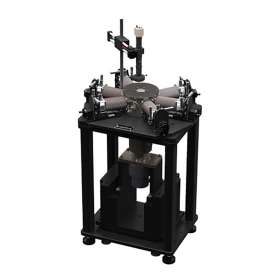
Lake Shore Cryotronics CRX-6.5K User Manual (166 pages)
Probe Station
Brand:
Lake Shore Cryotronics
| Category:
Power Supply
| Size: 8.17 MB
Table of Contents
Table of Contents
5
General
11
Product Description
11
Specifications
12
Station Details
14
Safety Considerations
15
General
17
System Overview
17
Major Components
17
Probe Station
18
Vacuum Chamber and CCR Vacuum Shroud
19
Sample Cooling Assembly
20
Will Not Achieve
20
Closed Cycle Refrigerator (CCR)
21
Micro-Manipulated Stages
22
Temperature Controller
23
Pressurized Gas System
24
Vision System
25
Turbo Pumping System (Optional TPS-FRG or Equivalent)
25
Configurations, Options and Accessories
26
Probing Configurations
26
DC/RF (ZN50) Probe Configurations
26
ZN50 Probes
26
ZN50-Compatible Probe Cables and Connectors
27
ZN50-Compatible Probe Mount
28
Microwave Probe Configurations
28
Microwave-Compatible Probes
28
Microwave-Compatible Cables and Connectors
29
Microwave Calibration Substrate
29
Optical Fiber Assembly
30
Sample Holders
30
Grounded Sample Holders
30
Isolated Sample Holders
30
Coaxial Sample Holders
31
Triaxial Sample Holders
31
Vision System Configuration
31
Microscopes
31
Lighting Types
32
Turbo Pumping System (TPS-FRG) and Pumping Kit (PS-TP-KIT)
33
High Temperature Option (PS-HTSTAGE)
34
Pump Line Vibration Isolator (PS-PLVI-40)
34
Recirculating Chiller Option (RC-EM10)
34
Considerations for DC/RF Electrical Measurements
35
Grounding Shielding, and Isolation for DC/RF Measurements
35
Ground Reference
35
Avoiding Ground Loops
36
Shielding
37
Noise Isolation
37
Basic DC Electrical Measurements
38
Basic RF Electrical Measurements
39
Conductive Back Side Features
39
Back Side Voltage Biasing
40
Small Signal/Low Noise DC/RF Measurements
40
Noise Isolation for Low Noise Measurements
40
Sample Isolation for Low Noise Measurements
41
Additional Considerations for Low Noise Measurements
41
Measuring Low Resistance
41
High Impedance/Low Leakage Measurements
42
Grounding and Shielding
42
Driven Guards
42
Guarded Probe Station Configurations
43
Measurement Voltage Limits
44
Considerations for Microwave Measurements
45
Microwave Cables and Connectors
45
Ground Return Path
46
Pad Construction and Impedance Matching
47
Probe Crosstalk
47
Calibration with the CS-5 Calibration Standard
48
Temperature Effects of Calibration
49
Planarization
50
Contact Quality
50
Contact Material
50
Contact Area
50
Oxidation
51
Four-Lead Measurement
51
Ohmic Versus Non-Ohmic Contacts
51
Measuring Contact Quality
51
Lab Protocol
51
General
53
Installation and Setup
53
Lake Shore Assisted Installation
53
Site Requirements
53
Space Requirements and Suggested Layout
54
Environmental Requirements and Concerns
55
Vibration
55
Electrical Noise
55
Ventilation
55
Safety Compliance
55
Power Requirements
56
Water Requirements
57
Water Flow and Temperature
57
Water Quality
57
Water Routing and Connections
58
Vacuum Requirements
58
Gas Requirements
58
Unpacking the Probe Station
59
Shipping Containers
59
Inspecting for Shipping Damage
59
Required Tools
59
Moving and Lifting the Probe Station
60
Uncrating the Probe Station
60
Unpacking the Probe Station
63
Unpacking the Equipment
63
Unpacking the Model 336 Temperature Controller
63
Unpacking the Vision System
63
Unpacking the Tool Kit and Spares Kit
63
Unpacking the Probe Starter Kit
64
Unpacking the CCR Compressor and Components
64
Inspecting the CCR Components
65
Unpacking the Options
65
Utility Connections
66
Power Connections
66
Cooling Water Connections
66
Pre-Assembly Testing
67
Testing the Turbo Vacuum Pumping System
67
Assembling a Basic Probe System Configuration
68
Positioning and Leveling the CCR Stand
68
Connecting the CCR Compressor to the Probe Station
69
Flexible Helium Line Connection
70
Cold Head Electrical Cable Connection
71
Connecting the Probe Station
72
Probe Station Connections
72
Assembling the Vision System
73
Assembling the Vertical Post
73
Assembling the Microscope and Horizontal Boom
74
Connecting the Vision System
75
Assembling the Turbo Pumping System
77
Preparing the Probe Station before Attaching the Vacuum
77
Preparing the Turbo Vacuum Pump
77
Assembling Probe Station Options
79
Assembling the Pump Line Vibration Isolator (PS-PLVI-40)
79
Installing and Removing Probes
80
Installing a Probe: Prep Instructions for All Probe Types
80
Installing a ZN50 Probe
80
Installing the ZN50 Probe Mount
81
Installing the ZN50 Probe Blade
82
Removing a ZN50 Probe
83
Removing the ZN50 Probe Blade
83
Removing the ZN50 Probe Mount
85
Installing a Microwave Probe
85
Removing a Microwave Probe
87
System Verification and Testing
88
Instrumentation Verification
88
Verifying Voltages
88
Verifying Power on
88
Verifying the Model 336 Temperature Controller Settings
88
Temperature Sensor and Heater Test
88
CCR Operation Test
89
Microscope Light and Focus Test
90
Testing the Probe Arm Reach
90
Probe Continuity Test
90
Vacuum Chamber Leak Test
91
General
93
Basic Operation
93
Common Operational Mistakes
93
Temperature Limits
93
Operating the Probe Arm Translation Stages
94
Sample Exchange
96
Opening the Vacuum Chamber and Radiation Shield
96
Removing the Sample Holder
97
Mounting Samples on the Sample Holder
98
Sample Alignment and Position
98
Reducing the Risk of Cracking Wafers
98
Temporary Mounting
98
Semi-Permanent Mounting
99
Permanent Mounting
100
Mounting the Sample Holder Onto the Sample Stage
100
Closing the Vacuum Chamber and Radiation Shield
101
Vacuum Operation
102
Turbo Pump Overview
102
Vacuum Controls
102
Vacuum Gauge Location
103
Vacuum Performance
103
Evacuating the Vacuum Chamber
104
Shutting down the Turbo Pump
104
Purging the Vacuum Chamber
105
Temperature Operation
106
Controls for Temperature Operation
106
CCR Controls
106
Electronic Temperature Controls
107
Cooling the Probe Station
107
Preparing the System
107
Starting the CCR
107
Allowing the Sample and Radiation Shield Stages to Cool
108
Operating the Sample Stage from Base Temperature to 350 K
108
Returning to Room Temperature
109
Temperature Control Summary
109
Imaging and Probing the Sample
111
Using the Microscope to Image the Sample
111
Landing the Probe
112
Using the Planarization Assembly
113
Adjusting the Angle of the Planarization Assembly
113
General
115
Advanced Operation
115
Advanced Temperature Operation
115
Reducing Condensation on the Sample
115
Heated Cycle Purge
115
While Cooling the Probe Station
116
High Temperature Sample Stage Operation
116
Configuring the Model CRX-6.5K for High Temperature
116
Sample Stage Operation
116
HT Sample Stage Installation
118
HT Sample Stage Removal
119
Reconfiguring the Model CRX-6.5K for Standard Operation
119
Temperature Operation with the HT Sample Stage
120
Probe Arm Assembly Reconfiguration
121
Installing a Micro-Manipulated Translation Stage (MMS-07)
121
Removing a Micro-Manipulated Translation Stage (MMS-07)
123
Removing a Probe Arm and Base
124
Installing a Probe Arm and Base
126
Reconfiguring Ultra-Miniature Cryogenic Coaxial Cables
127
Removing an Ultra-Miniature Cryogenic Coaxial Cable
127
Installing an Ultra-Miniature Cryogenic Coaxial Cable
127
Reconfiguring Microwave Cables
129
Removing a Microwave Cable
129
Installing a Microwave Cable
129
Adjusting the Fit of Microwave Cables
130
Reconfiguring an Optical Fiber Assembly
132
Removing an Optical Fiber
132
Installing an Optical Fiber Assembly
132
Installing the Planarization Assembly
135
General
137
Maintenance and Troubleshooting
137
Maintenance
137
Preventive Maintenance Schedule
137
Cleaning the Vacuum Chamber Exterior
138
Cleaning the Vacuum Chamber Interior
138
Viewport Window Maintenance
139
Cleaning the Viewport Windows
139
Fogging the Viewport Windows
139
O-Ring Maintenance
139
Re-Greasing O-Rings
139
Accessing Other O-Rings
140
Cleaning the Sample Holder
140
Cleaning Becu Probe Tips
141
Cleaning Microwave Probe Points
142
General Cleaning
142
Removing Oxidation
142
Probe Arm Maintenance
142
CCR Maintenance
143
Charging the CCR Compressor Helium Gas
143
CCR Cold Head 10,000 Hour Maintenance
143
CCR Compressor Oil Mist Adsorber 30,000 Hour Maintenance
143
Vacuum Pump Maintenance
143
Turbo Pumps
143
Scroll Pumps
143
Oil Mist Eliminators
143
Diaphragm Pumps
144
Removing Condensation from Inside the Vacuum Chamber
144
Troubleshooting Procedures
145
Vacuum Troubleshooting
145
Testing the Turbo Vacuum Pump Alone
146
Connection to the Probe Station
146
Testing the Vacuum Pumping System, the Connection to the Probe Station and the Probe Station Vacuum Chamber
147
The Impact of Cryopumping
147
Vacuum Chamber Leak Test
147
Will Not Achieve
148
Torr
148
Will Not Achieve Less than
149
Torr or Cool to 10 K
149
CCR Troubleshooting
150
Probe Station Cooling Troubleshooting
150
Probe Station Does Not Begin to Cool
150
Sample Stage will Not Cool
150
Radiation Shield Stage will Not Cool
150
Sample Stage Does Not Reach Base Temperature
150
Takes too Long to Cool
151
Erratic Temperature Readings
151
Image System Troubleshooting
152
No Image
152
Insufficient Sample Illumination
152
Poor Image Quality
152
Fog on the Viewport
152
Height Adjustment
153
Vibration in the Image System
153
Poor Contrast Images
154
Image Orientation
154
Probe Troubleshooting
155
Bent or Broken Probe Tips
155
Poor or Non-Ohmic Electrical Contact
156
Loss of Continuity
156
Service Reference
157
Power Requirements
157
Pin Outs
158
Instrumentation Wiring Diagram
159
Technical Inquiries
161
Contacting Lake Shore
161
Return of Equipment
161
RMA Valid Period
161
Shipping Charges
161
Restocking Fee
161
Advertisement
Advertisement
Related Products
Lake Shore Cryotronics 1015
Lake Shore Cryotronics 121
Lake Shore Cryotronics Categories
Measuring Instruments
Power Supply
Temperature Controller
Controller
Thermometer
More Lake Shore Cryotronics Manuals
Login
Sign In
OR
Sign in with Facebook
Sign in with Google
Upload manual
Upload from disk
Upload from URL