Sign In
Upload
Manuals
Brands
Laars Manuals
Boiler
NT2 V 0399
Laars NT2 V 0399 Manuals
Manuals and User Guides for Laars NT2 V 0399. We have
1
Laars NT2 V 0399 manual available for free PDF download: Assembly, Installation And Operation Instructions
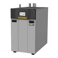
Laars NT2 V 0399 Assembly, Installation And Operation Instructions (116 pages)
Modulating Boiler and Volume Water Heater
Brand:
Laars
| Category:
Boiler
| Size: 9 MB
Table of Contents
Table of Contents
2
Rating Plate
4
Section 1 General Information
4
B Warranty
4
A Introduction
4
D Model Identification
5
E Safety Notes
6
F Model Overview
8
G Dimensions
10
A Removing Boiler from Existing Common Vent
12
Section 2 Locating the Unit
12
B Unpacking and the Install Kit
13
D Outdoor Installation
13
C Locating the Unit
13
Clearances
14
A General Venting Information
14
Section 3 Venting and Combustion Air
14
Venting Safety Warnings
15
B Flue Gas Sampling Port
15
C Approved Materials
16
C.2.A Polypropylene Adapters & Terminations
17
Polypropylene
17
C.1.B PVC/CPVC Concentric Terminations
17
Pvc/Cpvc
17
C.1.A PVC/CPVC Terminations
17
Stainless Steel
18
C.3.A Stainless-Steel Adapters & Terminations
18
D Sizing
20
Category IV Vent Sizing
20
Category Ll Vent Sizing
21
E Air for Combustion and Ventilation
22
Combustion Air from Room
22
Ducted Combustion Air
22
Side Wall Terminations
23
Locating Terminations
23
F.1.B Side Wall Concentric Terms (399 - 500 Only)
24
Vertical Terminations
26
G Installations in the Comnwlth of Massachusetts
27
SECTION 4 GAS SUPPLY and PIPING 4.A Gas Supply and Piping
27
B Gas Pipe Sizing
28
A Boiler Flow and Head Requirements
29
B Water Heater Flow and Head Requirements
29
C Water Heater Recovery Data
30
Boiler Cold Water Make-Up
31
A Install the PRV & Temp/Pressure Gauge
31
B Boiler Piping
31
Section 6 Water Piping
31
Boiler Suggested Piping Schematics
32
Freeze Protection
32
C Water Heater Piping
39
Water Quality
39
Piping Requirements
39
Cold Water Make-Up
39
Freeze Protection
39
Heater Suggested Piping Schematics
39
B Condensate Level Error
42
A Condensate Trap Installation
42
Section 7 Condensate Drain Trap
42
A Installation Warnings
43
B Main Power Ratings
43
C Wiring
44
D Control Panel Layout
45
RS485 for Cascade (Lead Lag)
46
RS485 for BMS
46
Dry Contacts (Run & Alarm)
46
Alarm Bell
46
Pump Contacts (Dry)
46
E Field Connections
46
Safety Interlocks
47
Heat Demands
47
Sensor Inputs
47
Analog Output, Pump
48
Analog BMS
48
Auxiliary 24VAC Power
48
F Modbus/Bacnet Memory Map
49
G Wiring Diagram
52
Logic Diagram
53
SECTION 9 USING the TOUCH SCREEN 9.A the Home Screen
54
Keypad Operations
55
B Login to Lock / Unlock the Display Screen
56
C Quick Start
57
Central Heat)
57
C.1.A CH1 (Central Heat, One) 1
58
C.1.B CH2 (Central Heat, Two)2
58
DHW (Domestic Hot Water)
58
Outdoor Reset
59
Warm Weather Shut down
59
Time & Date
60
Anti-Short Cycle
60
D Configuration
61
Central Heat)
62
D.1.A CH1 (Central Heat, One) 1
62
D.1.A.1 PID Low
63
D.1.A.2 PID High
63
D.1.B CH2 (Central Heat, Two) 2
63
DHW Parameters (Domestic Hot Water)
64
Outdoor Reset
65
Cascade
66
D.4.A Cascade Parameters
71
D.4.A.1 Base / Drop Load
72
D.4.B Rotation
72
D.4.B.1 Rotation Setup
73
D.4.C Redundancy
73
Pumps
74
D.6.A VARI-PRIME
75
Manual Firing Rate
76
Temp Limits
76
D.8.C Outlet Limitation Parameters
77
D.8.B Flue Limitation Parameters
77
D.8.A Delta T Parameters
77
External
78
D.9.A External - Remote Set Point
79
D.9.B External Firing Rate
80
Time & Date
80
Miscellaneous Features
81
D.11.A Demands Priorities
82
D.11.B Anti-Short Cycle
82
D.11.C Warm Weather Shutdown
83
D.11.D COM Port, BMS
84
D.11.E Temperature Conversion
85
D.11.F Anti-Frost
85
Login
86
E Service Screens
86
Burner
87
E.1.A Enable / Disable
87
E.1.B Altitude Adjustment
87
Digital I/O ( Input / Output )
88
Analog I/O
89
Both Model OEM Only
90
BIC Model OEM Only
90
HMI Model OEM Only
90
Factory Reset
90
Restart Touchscreen & Recalibrate
90
History
90
Screen Settings Timeout
90
About about the Firmware
91
F Messages and USB
91
Messages
91
USB Functionality
91
G Active Demands
92
Section 10 Parameter Tables
93
A Boilers
93
B Volume Water Heaters
96
Section 11 First Start up & Adjustment
98
A Filling the Boiler System
99
B Altitude Adjustment
99
C Initial Operation
99
Initial Burner Operation
99
D Combustion Setup
100
E Shutting down the Unit
101
F Restarting the Unit
101
A Annually
102
B Maintenance Notes by Component
102
Heat Exchanger and Burner
102
Condensate Trap
103
Air Filter
103
Gas Valve
104
Spark and Flame Sensor Electrodes
104
Blower
105
Control
105
Touchscreen Display
105
Flow Switch
105
Start
106
Pre-Purge
106
Standby
106
Pressure Transmitters
106
Gas Pressure Switches (Optional)
106
SECTION 13 TROUBLESHOOTING 13.A Sequence of Operation
106
Prespark
107
Ignition
107
Run
107
Interpurge
107
Postpurge
107
Open Safety Chain
107
Lockout
107
B Error Codes
110
C Index
115
Advertisement
Advertisement
Related Products
Laars NT2 V 0500
Laars NT2 V 0650
Laars NT2 V 0800
Laars NT2 v 0999
Laars NT2 V 1500
Laars NT2 H 0399
Laars NT2 H 0500
Laars NT2 H 0650
Laars NT2 H 0999
Laars NT2 H 1500
Laars Categories
Boiler
Water Heater
Industrial Equipment
Swimming Pool Heater
Heater
More Laars Manuals
Login
Sign In
OR
Sign in with Facebook
Sign in with Google
Upload manual
Upload from disk
Upload from URL