Sign In
Upload
Manuals
Brands
Laars Manuals
Boiler
MINI-THERM JX-75 Series
Laars MINI-THERM JX-75 Series Manuals
Manuals and User Guides for Laars MINI-THERM JX-75 Series. We have
1
Laars MINI-THERM JX-75 Series manual available for free PDF download: Installation And Operation Instructions Manual
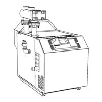
Laars MINI-THERM JX-75 Series Installation And Operation Instructions Manual (52 pages)
Residential Gas-Fired Hydronic Boilers Sizes 50-200 MBTU/h
Brand:
Laars
| Category:
Boiler
| Size: 5.1 MB
Table of Contents
Table of Contents
2
SECTION 1 GENERAL INFORMATION 1.A Safety Warnings
4
B Introduction
6
C Warranty
6
Model Number and Nomenclature
6
E Model Overview
7
F Dimensions
9
G the Installation Kit
10
H Accessory Kits Available
10
SECTION 2 LOCATING the BOILER 2.A Field Assembly
10
B Boiler Placement
10
C Clearances
10
SECTION 3 AIR and VENTING 3.A Safety Warnings
11
B Combustion Air Supply
12
C Venting
13
D Vertical Venting - Category I
14
E Locations for Vent Pipe Terminator
15
F Venting with a Power Venter
16
G Common Vent Test
16
SECTION 4 GAS CONNECTIONS 4.A Gas Supply and Piping
17
BLP Gas Conversion
18
C Special Precautions for LP Gas
18
Section 5 Pump Requirements
19
A Pump Sizing
19
SECTION 6 WATER CONNECTIONS 6.A Water Piping
20
B Low Loss Header
20
C Chilled Water Systems
20
D Oxygen Permeable Systems
20
E Anti-Freeze
20
Typical Plumbing Diagrams
21
AND Safety Warnings
23
B Main Power, 120V
23
C Outdoor Sensor
23
D Field Connections
24
TB1 (Term Block 1 -TT, DHW, OAS)
24
D.1.A TT (Central Heat)
24
D.1.B DHW
24
D.1.C Field Interlocks
24
D.1.D PV Terminals
24
D.1.E WWSD + COM
24
D.1.F OAS + COM
24
TB2 (for Pumps and Aux Power)
25
D.2.A Boiler Pump
25
D.2.B SYS Pump
25
D.2.C Aux Power
25
TB3 (for Optional Equipment)
25
D.3.A DHW Pump
25
D.3.B DHW Aquastat
25
E Wiring Connects, Power Vent and Air
26
F Wiring Diagram
28
G Logic Diagram
29
Section 8 the Digital Dashboard
30
A Getting to Know the Digital Dashboard
30
Setting the Economy Feature
30
High Limit (High Temp)
30
Low Limit (Advanced Options/Adjust)
30
A.4.A ACTIVE (TEMP)
30
A.4.B HI TEMP
30
A.4.C ACTIVE (LWCO)
30
Control Leds
31
A.4.D LOW WATER
31
A.4.E ACTIVE (ECONOMY)
31
A.4.F TARGET
31
Digital Leds
31
Ignition Leds
31
A.6.A LIMITS
31
A.6.B V-PWR
31
A.6.C V-SW
31
A.6.D FLAME
32
B Default Settings
32
C Advanced Settings
32
Programming the Outdoor Sensors
32
C.1.A Setting the Outdoor Reset
32
C.1.B Setting Warm Weather Shutdown
32
C.1.D Thermal Boost
33
Degrees Fahrenheit or Celsius
34
Manual Reset Low Water Cut-Off
34
Low Water Cut-Off
34
High Limit Differential
34
Restore Factory Default Settings
34
TEST/SETTINGS Button
35
E Temperature and Pressure Gauge
35
Section 9 Initial Startup
36
A Filling the System
36
B System Start up (Seq of Operation)
36
C Proper Pilot Flame
38
D Lighting Instructions Decal
39
E System Shutdown
40
SECTION 10 MAINTENANCE 10.A Removing the Covers and Panels
40
Access Cover Removal
40
Flue Collector Access
40
Side Panel Removal
41
Draft Hood Removal
41
B Maintenance
42
Operating Details and Troubleshooting
43
A Operating Details
43
B Electrical Troubleshooting
43
C Troubleshooting Table
44
Troubleshooting Flow Chart 1 (Burners Off)
45
Troubleshooting Flow Chart 2 (Burners On)
46
A Parts Illustrations
47
B Parts List
49
C Accessories List
50
D Glossary of Terms
51
Advertisement
Advertisement
Related Products
Laars JVS
Laars JVT
Laars MINI-THERM JX-50 Series
Laars MINI-THERM JX-100 Series
Laars MINI-THERM JX-125 Series
Laars MINI-THERM JX-150 Series
Laars MINI-THERM JX-200 Series
Laars MINI-THERM JX Series
Laars 1487
Laars 1505
Laars Categories
Boiler
Water Heater
Swimming Pool Heater
Industrial Equipment
Heater
More Laars Manuals
Login
Sign In
OR
Sign in with Facebook
Sign in with Google
Upload manual
Upload from disk
Upload from URL