Sign In
Upload
Manuals
Brands
Laars Manuals
Boiler
MagnaTherm HTD Series
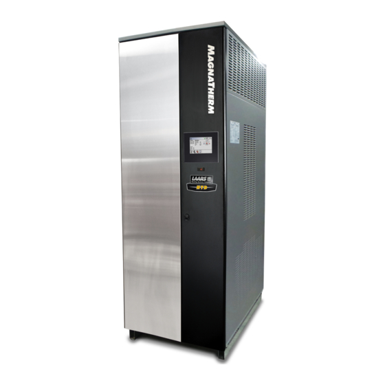
Laars MagnaTherm HTD Series Manuals
Manuals and User Guides for Laars MagnaTherm HTD Series. We have
2
Laars MagnaTherm HTD Series manuals available for free PDF download: Installation And Operation Instructions Manual
Laars MagnaTherm HTD Series Installation And Operation Instructions Manual (144 pages)
Boilers and water heaters
Brand:
Laars
| Category:
Boiler
| Size: 10.15 MB
Table of Contents
Table of Contents
2
SECTION 1 General Information
5
A Introduction
5
B Model Identification
5
C Warranty
5
D Safety Notes
6
E Unit Overview
8
F Gas Train Components
9
G Venting Dimensions & Sizing
10
H Dimensions
10
I Unpacking and the Install Kit
12
J Locating the Unit
12
K Clearances
13
SECTION 2 Venting and Combustion Air
14
A General Venting Information
14
B Vent and Air Pipe Material
14
Venting Reqs Unique to Canada
14
B.1.A Flue Gas Sampling Port
14
B.1.B Exhaust Vent Terminal
15
C Vent and Air Pipe Sizing
16
Category Lv Vent Sizes
17
Category II Vent Sizes
17
Common Venting
17
Common Vent Test
18
Combustion Air
19
C.5.A Combustion Air from Room
19
C.5.B Ducted Combustion Air
20
D Locating the Vent
20
Locating the Vent and Combustion Air Terminals
20
Side-Wall Vent Terminal
20
Side-Wall Combustion Air Terminal
22
Vertical Vent Terminal
22
Vertical Combustion Air Terminal
22
E Outdoor Installation
23
F Installations in the Commonwealth of Massachusetts
23
SECTION 3 Gas Supply and Piping
24
A Gas Supply and Piping
24
B Gas Pipe Sizing
25
SECTION 4 Water Flow & Headloss Data
26
General Water Flow Information
26
B Boiler Water Flow & Headloss Data
26
C Water Heater Water Flow and Headloss Data
27
SECTION 5 Piping
28
Boiler Water Piping
28
Boiler Water Connections
28
Cold Water Make-Up
28
Freeze Protection
28
Suggested Boiler Piping Schematics
29
Water Heaters
33
Water Quality
33
Heater Water Connections
33
Cold Water Make-Up
33
Freeze Protection
34
Suggested Piping Schematics
34
SECTION 6 Condensate Drain Trap
36
Condensate Trap Instructions
37
SECTION 7 Electrical Connections
38
Installation Warnings
38
Main Power Connections
39
Main Power Data
40
Control Panel Layout
40
Field Connections
40
Power
40
Dry Contacts
40
Temperature Sensors
42
Heat Demands
43
Analog in and Analog out
43
Dry Contacts. Run & Alarm
43
RS 485, Cascade
44
Rs485 Bms
44
Modbus to Bacnet Memory Map
45
Wiring Diagrams
48
High Voltage Wiring Diagrams
52
Ladder Diagrams
59
SECTION 8 Control Operation
66
The Home Screen
66
Home Screen Active Icons
66
Keypad Operations
67
Login to Lock / Unlock the Display
68
Quick Start
69
Quick Start CH (Central Heat)
69
Quick Start CH1 (Central Heat, One)
70
Quick Start CH2 (Central Heat, Two) . 66 Quick Start DHW (Dom Hot Water)
70
Outdoor Reset
71
Warm Weather Shut down
71
Anti-Short Cycle
72
Time & Date
72
D Configuration
73
CH (Central Heat)
74
D.1.A CH1 (Central Heat, One)
74
D.1.A.3 PID Parameters
75
D.1.B CH2 (Central Heat, Two)
75
DHW (Domestic Hot Water)
75
Outdoor Reset
76
Cascade (Lead / Lag)
77
D.4.A Cascade CH (Central Heat)
82
D.4.A.1 Cascade CH Lead Settings
83
D.4.A.1.A Cascade Base / Drop Load
84
D.4.B Cascade DHW (Dom Hot Water)
84
D.4.C Cascade Rotation
85
D.4.C.1 Cascade Rotation Setup
85
D.4.D Cascade Redundancy
86
Hybrid
86
Pumps
87
D.6.A DHW Recirculation
88
D.6.B VARI-PRIME
88
Manual Firing Rate
89
Temp Limits
89
D.8.A Delta T Parameters
90
D.8.B Flue Limitation Parameters
90
D.8.C Outlet Limitation Parameters
90
External
91
D.9.A External - Remote Set Point
92
D.9.B External Firing Rate
93
Time & Date
93
Miscellaneous Features
94
D.11.A Demand Priority
95
D.11.B Anti-Short Cycle
95
D.11.C Warm Weather
96
D.11.D COM Port, BMS
97
D.11.E Temperature Conversion
98
D.11.F Anti-Frost
98
D.11.G Trim (O 2 Trim Enable / Disable)
99
Login
99
E Service Screens
100
Burner
100
Digital I/O ( Input / Output )
101
Analog I/O
102
Screen Settings Timeout
103
History
103
Restart Touchscreen & Recalibrate
103
Factory Reset
104
HMI Model OEM Only
104
BIC Model OEM Only
104
Both Model. OEM Only
104
About about the Firmware Version
104
O2 (Trim Set Point)
104
Lmv
104
Messages and USB
105
Messages
105
USB Functionality
105
Active Demands
106
SECTION 9 Parameter Tables
107
SECTION 10 Initial Startup Instructions
113
Filling the Boiler System
113
Initial Operation
114
Initial Burner Operation
114
Combustion Setup Procedure Hi Fire, Low Fire
115
Shutting down the Unit
117
Restarting the Unit
117
Controllers
117
Transmitters
118
SECTION 11 Maintenance
119
System Maintenance
119
Maintenance Notes
119
Burner
119
Gas Train Components
119
Controller
120
Spark Ignition Electrodes
120
Flame Sensor
120
Blower Model 1600
120
Blower Model 2000-4000
120
Heat Exchanger Tubes
121
Gas Pressure Switches
121
Pressure Transmitters
122
Oxygen Sensor
122
High Temperature Limits (Optional)
122
SECTION 12 Troubleshooting
123
Lockouts and Errors
123
LMV Errors
125
SECTION 13 Replacement Parts
130
General Information
130
Component Illustrations, Parts Lists, and Part Numbers
130
Advertisement
Laars MagnaTherm HTD Series Installation And Operation Instructions Manual (132 pages)
Brand:
Laars
| Category:
Boiler
| Size: 28.6 MB
Table of Contents
Table of Contents
2
SECTION 1 General Information
5
A Introduction
5
B Model Identification
5
C Warranty
5
D Safety Notes
6
E Unit Overview
8
F Gas Train Components
9
G Venting Dimensions & Sizing
10
H Dimensions
10
I Unpacking
12
J Locating the Unit
12
K Clearances
13
SECTION 2 Venting and Combustion Air
14
A General Venting Information
14
B Vent and Air Pipe Material
14
B.1.A Flue Gas Sampling Port
14
B.1.B Exhaust Vent Terminal
15
C Vent and Air Pipe Sizing
16
Category Lv Vent Sizes
17
Category II Vent Sizes
17
Common Venting
17
Common Vent Test
18
C.5 Combustion Air
19
Combustion Air
19
C.5.A Combustion Air from Room
19
C.5.B Ducted Combustion Air
20
D Locating the Vent
20
Locating the Vent and Combustion Air Terminals
20
Side-Wall Vent Terminal
20
Side-Wall Combustion Air Terminal
22
Vertical Vent Terminal
22
Vertical Combustion Air Terminal
22
E Outdoor Installation
23
Installations in the Commonwealth of Massachusetts
23
SECTION 3 Gas Supply and Piping
24
A Gas Supply and Piping
24
B Gas Pipe Sizing
25
SECTION 4 Water Flow and Headloss Data
26
A General Water Flow Information
26
B Boiler Water Flow & Headloss Data
26
C Water Heater Water Flow and Headloss Data
27
SECTION 5 Piping
28
Boiler Water Piping
28
Boiler Water Connections
28
Cold Water Make-Up
28
Freeze Protection
28
Suggested Boiler Piping Schematics
29
Water Heaters
33
Water Quality
33
Heater Water Connections
33
Cold Water Make-Up
33
B.4 Freeze Protection
34
Freeze Protection
34
Suggested Piping Schematics
34
SECTION 6 Condensate Drain Trap
36
SECTION 7 Electrical Connections
37
Installation Warnings
37
B Main Power Connections
38
Control Panel Layout
38
C Control Panel Layout
39
Field Connections
39
Power
39
Dry Contacts
39
D.3 Temperature Sensors
40
Temperature Sensors
40
Heat Demands
40
Analog in and Analog out
41
Dry Contacts. Run & Alarm
41
RS 485, Cascade
42
Rs485 Bms
42
D.7 RS 485, Cascade
42
Modbus to Bacnet Memory Map
43
Wiring Diagrams
46
High Voltage Wiring Diagrams
50
Ladder Diagrams
57
SECTION 8 Control Operation
64
Home Screen Active Icons
64
A.2 Keypad Operations
65
Keypad Operations
65
B Login to Lock / Unlock the Display
66
C Quick Start
67
Quick Start
68
C.2.A CH1
68
Ch2
68
Dhw/Dhw3
68
C.3 Outdoor Reset
69
Outdoor Reset
69
Warm Weather Shut down
69
Anti-Short Cycle
70
Time & Date
70
D Configuration
71
D.1 Ch
72
D.1.A CH1
72
D.1.A.1 Enable/Disable
72
D.1.A.2 Set Point
72
D.2
73
D.1.A.3 PID Parameters
73
D.1.B CH2-DHW1-DHW2
73
Dhw/Dhw3
73
D.3 Outdoor Reset
74
Outdoor Reset
74
D.4 Cascade
75
Cascade
75
D.4.A Cascade CH
76
D.4.A.1 Cascade CH Lead Settings
77
D.4.B Cascade DHW
78
D.4.C Rotation
78
D.4.D Redundancy
79
Hybrid
79
D.6 Pumps
80
Pumps
80
D.6.A DHW Recirculation
81
D.6.B VARI-PRIME
81
Manual Firing Rate
82
Temp Limits
82
D.8.A Delta T Parameters
83
D.8.B Flue Limitation Parameters
83
D.8.C Outlet Limitation Parameters
83
D.9 External
84
External
84
D.9.A External - Remote Set Point
85
D.9.B External Firing Rate
86
Time & Date
86
D.11 Miscellaneous Features
87
Miscellaneous Features
87
D.11.A Demand Priority
88
D.11.B Anti-Short Cycle
88
D.11.C Warm Weather
89
D.11.D COM Port, BMS
90
D.11.E Temperature Conversion
91
D.11.F Anti-Frost
91
D.12 Login
92
D.11.G Trim (Enable / Disable)
92
Login
92
E Service Screens
93
Burner
93
Digital I/O ( Input / Output )
94
E.3 Analog I/O
95
Analog I/O
95
Screen Settings Timeout
96
History
96
Restart Touchscreen & Recalibrate
97
Factory Reset
97
HMI Model OEM Only
97
Lmv
97
Messages and USB
98
Messages
98
USB Functionality
98
Active Demands
99
SECTION 9 Parameter Tables
100
SECTION 10 Initial Startup Instructions
106
Filling the Boiler System
106
Initial Operation
107
Initial Burner Operation
107
Combustion Setup Procedure
108
Shutting down the Unit
109
Restarting the Unit
109
Operation
110
SECTION 11 Maintenance
111
System Maintenance
111
Maintenance Notes
111
Burner
111
Modulating Gas Valve / Venturi
111
B.3 Controller
112
Controller
112
Spark Ignition Electrodes
112
Flame Sensor
112
Blower Model 1600
112
Blower Model 2000-4000
112
Heat Exchanger Tubes
113
Gas Pressure Switches
113
SECTION 12 Troubleshooting
114
SECTION 13 Replacement Parts
116
General Information
116
Component Illustrations, Parts Lists, and Part Numbers
116
Part Numbers
117
Advertisement
Related Products
Laars Mascot II
Laars MASCOT LX
Laars MASCOT FT MFTCW
Laars Mascot II LMC
Laars MASCOT II LMH
Laars mascot ft
Laars mascot ft MFTHW
Laars MagnaTherm MGH1600
Laars MFTHW
Laars MFTHW175
Laars Categories
Boiler
Water Heater
Industrial Equipment
Swimming Pool Heater
Heater
More Laars Manuals
Login
Sign In
OR
Sign in with Facebook
Sign in with Google
Upload manual
Upload from disk
Upload from URL