Sign In
Upload
Manuals
Brands
Kuhnke Manuals
Servo Drives
smartServo BL 4300-C connector set
Kuhnke smartServo BL 4300-C connector set Manuals
Manuals and User Guides for Kuhnke smartServo BL 4300-C connector set. We have
1
Kuhnke smartServo BL 4300-C connector set manual available for free PDF download: Product Manual
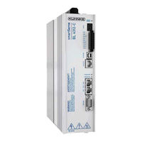
Kuhnke smartServo BL 4300-C connector set Product Manual (305 pages)
Brand:
Kuhnke
| Category:
Servo Drives
| Size: 8 MB
Table of Contents
Table of Contents
4
About this Product Manual
13
Explanations and Notation
13
Structure of the Warning Notes
13
Notation in this Product Manual
14
Additional Documents
14
Order Numbers
14
Applicable Standards
15
For Your Own Safety
16
General Information
16
Intended Use
17
Target Group
17
General Safety Instructions
18
Personal Protective Equipment
19
Safety Notes for Installation and Maintenance
19
Protection against Contact with Electrical Parts
21
Protection against Electric Shock by Way of Protective Extra-Low Voltage (PELV)
22
Protection against Dangerous Movements
22
Protection against Contact with Hot Parts
23
Protection During the Handling and Installation of the Devices
23
Product Description
24
Type Designation
24
Device View
25
Features
27
Quick-Start Guide
30
Using the Parameterisation Program
32
The User Interface
32
Setting up the Communication
33
Communication Via USB
33
Communication Via Ethernet
34
Changing the Communication Interface
36
Communication Errors
36
Numeric Input Fields for Changing Parameters Online
37
Operating Mode and Error Indication
38
Operability Check
39
Software-Guided Commissioning
40
General Configuration
41
Configuration of the Display Unit
45
Rotatory Operation
45
Translatory Operation
45
Other Setting Options
45
Adjusting the Input Limits
46
Configuration of the Motor Data
47
Safety Parameters
49
Motor Temperature Monitoring
52
Commutation Encoder
53
Angle Encoder Settings
54
Angle Encoder Identification (Automatic Determination)
55
Automatic Identification of the Current Controller
56
Configuring the Polarity of the Limit Switches
56
Configuration of the Speed Controller (Auto-Tuning with FAST)
57
Configuration of the Position Controller
59
Permanent Storage of the Parameters
61
Enabling the Servo Drive and Selecting the Set Values
62
Configuring the Enable Logic
62
Operating Modes
65
Torque-Controlled Mode (Torque Control)
65
Speed-Controlled Mode (Speed Control)
66
Position-Controlled Mode and Positioning Mode (Positioning Process)
67
Using the Servo Drive in Jog Mode
68
Selecting the Setpoints
69
Specifying the Setpoints (Speed and Torque Values)
70
Settings Concerning the Analogue Input AIN
71
Offset Calibration and "Safe Zero
72
Applications
73
Homing Process
73
Methods -17 and -18: Stop
74
Methods -1 and -2: Stop with Index Pulse Evaluation
74
Methods 17 and 18: Positive and Negative Limit Switch
75
Methods 1 and 2: Positive and Negative Limit Switch with Index Pulse Evaluation
75
Methods 23 and 27: Reference Switch
76
Methods 7 and 11: Reference Switch and Index Pulse Evaluation
77
Methods -23 and -27: Homing Run (Positive/Negative) to the Reference Switch
78
Methods 32 and 33: Homing to the Index Pulse
78
Method 34: Homing to the Current Position
79
Parameterisation of the Homing Method
79
Parameterisation of the Homing Run: Settings
80
Parameterisation of the Homing Run: Motion Profile
82
Tab: Index Pulse Control
83
Tab: Torques
84
Tab: Special Functions
85
Positioning Process
86
Global Positioning Settings
86
Destination Parameters: General Buttons
87
Destination Parameters: Settings Tab
88
Destination Parameters: Driving Profile Tab
90
Destination Parameters: Experts Tab
92
Moving to Specific Positions
95
Positioning Via Digital Inputs
95
Positioning Via the Parameterisation Interface (Usb/Ethernet)
95
Motion Program
97
Linking Positions
98
Global Settings
100
Digital Inputs - Motion Program
101
Jog Mode
102
Setting of Digital Outputs
103
Applications with Several Angle Encoders
104
Improved Position Control with Two Angle Encoders
105
Synchronisation/Parameterisation of the Master
106
Synchronisation/Parameterisation of the Slave
106
Position-Synchronous Operation
107
Special Considerations Concerning the Resolution of the Master Frequency
107
Flying Saw
108
Conventional Synchronisation
109
Parameterisation and Configuration
110
Synchronisation Activation and Deactivation (Example)
111
Starting Position/Position Set 0
111
Gripping of the Object/Position Set 1
112
Depositing of the Object/Position Set 2
113
Starting Position/Position Set 0
113
Wiring
114
Compensation of Constant Delays
114
Mechanical Compensation (Lead)
114
Compensation by Calculation
114
Triggering the Starting Process Based on Several Sources
115
Position Offset Due to Cycle Times
115
Lead of the Actual Position When the Light Barrier Is Not Located in the Range of Movement of the Drive
115
Summary
116
Rotary Axis Mode
117
Additional Settings
119
Bluetooth® Communication
119
Oscilloscope
120
Oscilloscope Window
120
Oscilloscope Settings
122
Tabs: CH1
122
Tabs: Time Base
124
Tabs: Trigger
125
Display Units
126
User-Defined Display Units
126
Direct Input of the Display Units
127
Parameter Sets
128
Online Parameterisation: Overview
128
Loading and Saving Parameter Sets
129
Offline Parameterisation
130
Parameterisation Via a Microsd Card
131
Angle Encoder Settings
134
Commutating-Generator" Tab
134
X2A" Tab
135
X2B/X6" Tab
136
General Settings
137
Digital Incremental Encoders
139
Analogue Incremental Encoders
141
Serial: Endat 2.2
143
Serial: HIPERFACE
144
Serial: HIPERFACE DSL
145
Serial: Biss
146
Storing Parameters in the Encoder
148
X1" Tab
151
Parameterisation of the Motor and Output Stage
153
Methods for Analysing Motor Problems
153
Configuration of the Output Stage
154
Use of Linear Motors
154
Fundamental Parameterisation of Linear Motors
155
Determining the Commutation Position in the Case of Linear Motors
158
Settings in the Homing Menu for Linear Motors
160
Necessary Error Reactions in the Case of Linear Motors
161
Manual Optimisation of the Controllers
162
Motor Requirements
162
Reversing Generator
164
Manual Speed Control Configuration
164
Manual Optimisation of the Position Controller
167
Digital Inputs
168
Configuration of the Digital Inputs
169
Digital Outputs
172
Configuration of the Digital Outputs
173
Configuration of the Messages for the Digital Outputs
174
Torque Message Window: "Comparison Torque
174
Speed Message Window: "Comparison Speed Reached
175
Target Position Message Window: "Xactual = Xtarget
176
Following Error Message Window: "Following Error
177
Position Triggers
178
Position Triggers
180
Rotor Position Triggers
181
Brake Control and Automatic Brake
182
Configuration of the DC Bus Monitoring Function
184
External Braking Resistor
185
DC Bus Coupling
186
Control Circuit Cycle Times
187
Band-Stop Filters
189
Motor Temperature Monitoring System
190
Parameterising the Characteristic (Linear/Non-Linear Sensor)
190
Temperature Limits and Monitoring Functions
191
Limit Switch, Setpoint Direction Limitation
192
Firmware Download
192
STO (Safe Torque Off)
193
Special Safety Instructions
193
Certification/Safety Level
193
Requirements for Using the Product
194
Qualification of the Specialist Personnel (Personnel Requirements)
194
Diagnostic Coverage (DC)
194
Purpose
195
Principle of Operation and Use
196
Description of the STO Safety Function
196
Overview of the [X3] Interface
197
Control Inputs STOA, GNDA/STOB, GNDB [X3]
198
Discrepancy Time
198
Test Pulses
199
Auxiliary Supply [X3]
199
Additional Diagnostics Functions
199
Circuit Examples
201
Safe Torque off (STO)
201
Deceleration and Safe Torque Switch off(SS1, "Safe Stop 1")
202
Prior to Commissioning
204
Kuhnke Servocommander® Safety Functions
204
Servo Drive Type Indication and Safety Function
204
Status Indication of the Finite State Machine
205
Safety Module (Integrated)" Window
206
Functional Test, Validation
207
Operation
207
Diagnostics and Fault Clearance
207
Fault Messages
208
Error Management
210
Error Buffer
211
Storage/Transport
212
Installation
213
Technical Data
215
General Technical Data
215
BL 4100-C: Power Supply [X9]
217
BL 4300-C: Power Supply [X9], [X9A], [X9B]
218
BL 4100-C: Motor Connector [X6]
219
BL 4300-C: Motor Connector [X6], [X6A]
222
Resolver Connector [X2A]
224
Encoder Connector [X2B]
225
Usb [X19]
228
Standard Ethernet [X18]
228
Real-Time Ethernet [X21]
228
CAN Bus [X4]
229
I/O Interface [X1]
229
Time Response of the Digital Inputs
232
Time Response of the Digital Outputs
233
Time Response During Power on
234
Sto [X3]
235
Electrical Data of the STO Function
235
Time Response
236
Time Response of the STO Activation During Operation with a Restart
236
Time Response of the SS1 Activation During Operation with a Restart
238
12.14 Microsd Card
239
Electrical Installation
240
Notes Concerning the Safe and EMC-Compliant Installation
240
Explanations and Terminology
240
General Information about Electromagnetic Compatibility
240
Proper Wiring
241
Operation with Long Motor Cables
242
ESD Protection
242
Additional Requirements for the UL Approval
243
BL 4100-C: Connector: Power Supply [X9]
244
BL 4300-C: Connector: Power Supply [X9], [X9A], [X9B]
246
BL 4100-C: Connector: Motor [X6]
249
BL 4300-C: Connector: Motor [X6], [X6A]
252
Connector: Resolvers/Analogue Hall Encoders [X2A]
255
Connector: Encoder [X2B]
257
Connector: USB [X19]
261
Connector: Standard Ethernet [X18]
262
Connector: Real-Time Ethernet [X21]
263
Connector: CAN Bus [X4]
264
Connector: I/O Interface [X1]
266
Connector: STO [X3]
268
Maintenance, Cleaning, Repair and Disposal
270
15 Appendix
271
CE Conformity (EMC, Rohs, Low Voltage Directive)
271
Safety Technology Glossary
271
CE Conformity (Machinery Directive)
273
Risk Reduction Questions
273
Culus Certification
277
Error Messages and Warnings
283
Advertisement
Advertisement
Related Products
Kuhnke smartServo BL 4000-C Series
Kuhnke smartServo BL 4308-C
Kuhnke smartServo BL 4312-C
Kuhnke smartServo BL 4100-C
Kuhnke smartServo BL 4102-C
Kuhnke smartServo BL 4104-C
Kuhnke smartServo BL 4304-C
Kuhnke 9200-4102-1000
Kuhnke 9200-4104-1000
Kuhnke 9200-4210-00
Kuhnke Categories
Touch terminals
Control Panel
Controller
Car Video System
Control Unit
More Kuhnke Manuals
Login
Sign In
OR
Sign in with Facebook
Sign in with Google
Upload manual
Upload from disk
Upload from URL