Sign In
Upload
Manuals
Brands
Kuhnke Manuals
Controller
KUAX 680C
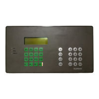
Kuhnke KUAX 680C Compact Controller PLC Manuals
Manuals and User Guides for Kuhnke KUAX 680C Compact Controller PLC. We have
2
Kuhnke KUAX 680C Compact Controller PLC manuals available for free PDF download: Instruction Manual
Kuhnke KUAX 680C Instruction Manual (221 pages)
Modules of Controllers
Brand:
Kuhnke
| Category:
Control Unit
| Size: 1 MB
Table of Contents
Table of Contents
3
1 Introduction
11
Manual Breakdown
12
Further Modules
13
2 Safety and Reliability
15
Target Group
15
Reliability
15
Notes
16
Danger
16
Dangers Caused by High Contact Voltage
16
Important Information / Cross Reference
16
Safety
17
To be Observed During Project Planning and Installation
17
To be Observed During Maintenance and Servicing
18
Electromagnetic Compatibility
19
Definition
19
Resistance to Interference
19
Interference Emission
20
General Notes on Installation
20
Protection against External Electrical Influences
21
Cable Routing and Wiring
21
Location of Installation
22
Particular Sources of Interference
22
3 Modules and Slots
23
Design
24
Screw-Type Locking Connectors
25
Coding
25
Slots
26
Function Slots
26
Service Modules
27
Transfer Address Ranges
27
Interrupt Modules
27
Power Supply of Inputs and Outputs
28
Differences between KUAX 680C/KDT 680CT and KUAX 680I
29
4 Digital Inputs and Outputs
31
Plugging Digital Input and Output Modules
32
Addressing (Input/Output Groups and Channels)
32
Reserved Slots
33
Digital Input Modules
34
Input Module, 24 V DC, 8 Inputs
35
Technical Specifications
36
Input Module, 24 V DC, 8 Inputs, with Real-Time Clock
37
Real-Time Clock
37
Parameters of KUBES Module "CLOCK
38
Programming Suggestion for the Real-Time Clock
40
4.2.2.4. Technical Specifications
41
Technical Specifications
41
Input Module, 24 V DC, 16 Inputs
42
Technical Specifications
43
Storage Temperature
43
Input Module, 24 V DC, 8 Inputs, 1 Ms
44
Technical Specifications
45
Input Module, 24 V DC, 16 Inputs, 1 Ms
46
Technical Specifications
47
Input Module, 24 V DC, 16 Inputs, Interrupt Capability
48
Signal Delay
48
Interrupt Inputs
50
4.2.6.3. Technical Specifications
53
Technical Specifications
53
Digital Output Module, 24 V DC, 0.5 A, 8 Outputs
54
Technical Specifications
56
Digital Input/Output Module, 24 V DC, 8/8
57
Inputs
57
Technical Specifications
58
(Incl. Residual Ripple)
58
Colour
58
Indicators
58
Input Voltage
58
LED on 0: LED off Addressing
58
Potential Separation
58
Surge Immunity
58
Tapping Point
58
Type (Acc. to IEC 1131)
58
Pneumatic Output Module, 4 Outputs 3/2 Way
59
Technical Specifications
60
5 Analogue Inputs and Outputs
61
Plugging Analogue Input and Output Modules
62
Addressing (Anal. Input/Output Groups and Channels)
62
Reserved Slots
63
Analogue Input Modules
65
Analogue Input Module, 0
65
Slots
65
Connectors
66
Representation of the Analogue Value
66
Technical Specifications
67
Analogue Input Module, 0(4)
68
Slots
68
Connections
69
Representation of the Analogue Value
69
Transfer Address Ranges
70
Technical Specifications
71
Admissible Ambient Conditions
71
Ambient Temp. During Operation
71
Inputs
71
Relative Humidity
71
Storage Temperature
71
Analogue Input Module, PT100, 0
72
Slots
72
Connectors
73
Transfer Address Ranges
74
Evaluation in the User Program
75
Technical Specifications
76
Part Number
76
Potential Separation
76
Weight
76
Analogue Input Module, Thermocouple Nicrni (Type K)
77
Slots
77
Connections
78
Transfer Address Ranges
79
Evaluation in the User Program
80
Technical Specifications
81
Analogue Input Module, Potentiometer, 10Bit, 4 Channels
82
Slots
82
Connectors
83
Representation of the Analogue Value
84
Technical Specifications
85
Analogue Output Modules
87
Analogue Output Module, 0
87
Slots
87
Connectors
88
Technical Specifications
89
Analogue Output Module, 0(4)
91
Slots
91
Connectors
92
Repesentation of the Analogue Value
92
Transfer Address Ranges
93
Technical Specifications
94
Analogue Input/Output Modules
95
Analogue I/O Module, 2 I 0
95
Slots
96
Connectors
97
Representation of the Analogue Value
98
Technical Specifications
99
Analogue I/O Module, 2 I 0
100
Slots
100
Connectors
101
Representation of the Analogue Value
102
Transfer Address Ranges of the Analogue Inputs
103
Technical Specifications
104
Analogue I/O Module, 2 I 0
105
Slots
106
Connectors
107
Representation of the Analogue Value
108
Transfer Address Ranges of the Analogue Inputs
109
Technical Specifications
110
Anal. I/O Module, 2 I 0
111
Slots
111
Connectors
112
Representation of the Analogue Value
113
Transfer Address Ranges
114
Technical Specifications
115
6 Counter Modules
117
Counter Module, 1 or 2 Multi-Function Counters, 24Bit
118
Functions
118
Slots
118
Counter Modules with 24V Inputs
119
Connectors
119
Technical Specifications
121
Counter Module with RS422 Interface
122
Connectors
122
Technical Specifications
123
Programming
124
Transfer Address Ranges and Interrupt Modules
124
Control Flags
126
Setting the Counter to the Preset Value / to 0
126
Setting the Reference Value
126
Counter Control
127
Reference Value
127
Interrupt
128
Counter Module, 2 Event Counters, 16Bit
129
Slots
129
Connectors
130
6.2.3. Technical Specifications
131
Technical Specifications
131
Programming
132
Transfer Address Ranges
132
Slot
132
Clearing the Count
134
Evaluating the Count
134
Selecting the Counting Direction
134
Selecting the Counting Mode
134
Setting the Counter to the Preset Value / to 0
134
Switching the Counter on / off
134
Slots
135
Function
135
SSI Module, 24 Bit, for 2 Absolute Value Devices
135
Connectors
136
6.3.3. Technical Specifications
137
Technical Specifications
137
Programming
138
Transfer Address Ranges
138
User Program
140
Clock Pulse Frequency
140
7 Communication Modules
141
RS 232) Module
141
Slots
141
Connector
142
Technical Specifications
143
Function
143
Part Number
143
Storage Temperature
143
Weight
143
TTY Module (20 Ma)
144
Slots
144
Connector
145
Technical Specifications
146
RS 485 Module
147
Slots
147
Connector
148
Technical Specifications
149
Part Number
149
Potential Separation
149
Weight
149
Programming the V.24, TTY and RS 485 Modules
150
Communication Programs SE 680I, KUSI680, RS485
150
KUBES Modules V24XE, V24XS, V24XSTRG
151
Parameters of the KUBES Modules
152
Example Program
155
PROFIBUS Modules
161
8 Stepper Motor Modules Without Processor
163
Plugging Stepper Motor Modules
164
Service Modules
165
Transfer Address Ranges
165
Assignment of Transfer Addresses
166
Software
167
Representation of a Run Diagram
167
Terminology and Functions
168
Start/Stop Ramp Slx01.08 (RAMP)
168
Start/Stop Frequency Slx01.10 (ST_STO_F)
168
Preset Value Step Counter Slx01.00 (SV_LW)
169
Mode of Positioning Operations Slx01.14 (MODE)
170
Control Functions Slx01.07 (CONTROL)
172
Error Messages
174
Stepper Motor Module, 1 Channel
175
Connection of the Signal Lines
175
Technical Specifications
178
9 Stepper Motor Module with Processor
187
Plugging Stepper Motor Modules
188
Service Modules
188
Transfer Address Ranges
188
Assignment of Transfer Addresses
189
Software
190
Representation of a Run Diagram
190
Terminology and Functions
191
Start/Stop Ramp Slx01.08 (RAMP)
191
Start/Stop Frequency Slx01.10 (ST_STO_F)
191
Travelling Frequency Slx01.12 (MOV_FRQ)
192
Actual Position Slx00.04 (RP_LW)
192
Destination Position Slx00.00 (DP_LW)
192
Preset Value Step Counter Slx01.00 (SV_LW)
193
Mode of Positioning Operations Slx01.14 (MODE)
193
Timing Diagrams of Run Jobs
195
Control Functions Slx01.07 (CONTROL)
196
Error Messages
198
Stepper Motor Module, 2 Channels
199
Connection of the Signal Lines
199
Technical Specifications
200
Example Program
201
Appendix
211
Power Consumption of the Modules
211
Power Supply
211
DC System Supply
211
Supply of Digital Outputs and Inputs
211
Load on the Power Supply by the Modules
212
Order Specifications
213
Literature List
215
Advertisement
Kuhnke KUAX 680C Instruction Manual (180 pages)
Compact Control
Brand:
Kuhnke
| Category:
Controller
| Size: 1 MB
Table of Contents
Table of Contents
3
1 Introduction
11
2 Safety and Reliability
13
Target Group
13
Reliability
13
Notes
14
Danger
14
Dangers Caused by High Contact Voltage
14
Important Information / Cross Reference
14
Safety
15
To be Observed During Project Planning and Installation
15
To be Observed During Maintenance and Servicing
16
Electromagnetic Compatibility
17
Definition
17
Resistance to Interference
17
Interference Emission
18
General Notes on Installation
18
Protection against External Electrical Influences
19
Cable Routing and Wiring
19
Location of Installation
20
Particular Sources of Interference
20
3 Hardware
21
Layout of Leds and Connectors
22
Top View
22
Front View
23
Screw-Type Locking Connectors
24
Coding
24
Basic Device: Dimensions and Mounting
25
Wall Mounting
25
Carrier Rail Mounting
26
Power Supply
27
Emergency off Installation for the Outputs
28
Interfaces for Serial Communication
31
Rs 232 (V.24)
31
Interface RS 232/1
32
Programming
32
Interface RS 485
32
User Memory
34
System Messages
35
A. Technical Specifications
35
Internal Inputs and Outputs
36
Digital Inputs, 5 Ms
37
Counter Inputs, 10 Μs
39
Interrupt Inputs, 300 Μs
42
Analog Inputs, 0
45
Digital Outputs, 500 Ma
47
Analog Outputs, 0
49
Module Slots
51
Differences to the KUAX 680I
52
Input / Output Configuration
53
The KUBES Module Configurator
54
Appendix
35
4 Software
55
Working Principle
55
Operands Overview
56
Short Description of the Operands
57
Commands Overview
59
Logical Operations Commands
59
Arithmetic Commands
65
Comparison Commands
66
Shift and Rotation Commands
67
Byte and Flag Manipulation
68
Module Calls
68
Jump Commands
69
Copy and BCD Commands
69
Programmable Pulses, Timers and Counters
70
Special Commands
71
Commands for the Initialisation Modules
71
Commands for the Data Modules
72
Registers
73
Addressing
73
Address Mnemonics
74
Offset Addressing
74
Addresses Occupied by the Operands
75
Types of Addressing: Overview
76
Description of the Commands
77
Logical Operations Commands
77
Load and Logical Operations Commands
77
Assignments and Set Commands
78
Arithmetic Commands
79
Comparison Commands
79
Shift and Rotation Commands
80
Byte and Flag Manipulation
81
Module Calls
81
Jump Commands
82
Copy and BCD Commands
83
Programmable Pulses (Edge Analysis)
84
Programmable Timers
85
Programmable Counters
86
Special Commands
87
Commands of the Initialization Modules
88
Commands of the Data Modules
89
Module Programming
91
Organization Module
92
Program Module
92
Function Module
95
Interrupt Module
95
Initialization Module
97
Data Module
97
Trigger Module
98
KUBES Module
98
Module Hierarchy (Example for Different Module Calls)
99
5 Networking
101
6 Programming Examples
103
Basic Functions
103
And
103
Negation at Input
104
Negation at Output
104
Nand
105
Nor
105
XO EXCLUSIVE-OR (Non-Equivalence)
106
XON EXCLUSIVE-NOR (Equivalence)
106
Self-Locking Circuit
107
Memory Functions
108
With Reset Dominance
108
With Set Dominance
108
Combinational Circuits
109
OR-AND Circuit
109
Parallel Circuit to Output
109
Network with One Output
110
Network with Outputs and Markers
111
S-Marker as AND/OR Marker
112
Network with or Marker
112
Network with and Marker
113
Network with Multiple Use of the or Marker
114
Circuit Conversion
115
Special Circuits
116
Current Surge Relay
116
Reverse Circuit (Reverse Contactor) with Forced Halt
117
Reverse Circuit (Reverse Contactor) Without Forced Halt
117
Pulse Edge Evaluation
118
Programmable Pulse with Positive Edge
118
Programmable Pulse with Negative Edge
119
Pulse with Positive Signal
120
Pulse with Negative Signal
121
Software Timers
122
Impulse at Startup
122
Impulse with Constant Duration
123
Raising Delay
124
Falling Delay
125
Impulse Generator with Pulse Output
126
Flash Generator with One Timer
127
Flash Generator with Two Timers
128
Programmable Clock
129
Software Counters
130
Programming of an Operational Sequence
130
Register Circuits
133
1Bit Shift Register
133
8Bit Shift Register
134
Bit-To-Byte Transfer
135
To Copy Eight 1Bit Operands into One Byte
135
To Copy One Byte into Eight 1Bit Operands
136
To Copy Sixteen 1Bit Operands into Two Bytes
136
To Copy Two Bytes into Sixteen 1Bit Operands
136
Comparator Circuits
137
8Bit Comparator
137
Result of the Comparison: Logical Evaluation
137
Result of the Comparison: Evaluation with One Jump
137
16Bit Comparator
138
Result of the Comparison: Logical Evaluation
138
Result of the Comparison: Evaluation with One Jump
138
Arithmetic Functions
139
Binary 8Bit Adder
139
Binary 16Bit Adder
139
8Bit BCD Adder
140
Binary 8Bit Subtractor
141
Binary 16Bit Subtractor
141
8Bit BCD Subtractor
142
Binary 8Bit Multiplier
143
Binary 16Bit Multiplier
143
Binary 8Bit Divider
144
Binary 16Bit Divider
144
Code Converters
145
8Bit BCD-To-Binary Converter
145
8Bit Binary-To-BCD Converter
146
16Bit BCD-To-Binary Converter
147
16Bit Binary-To-BCD Converter
148
Decade BCD-To-Binary Converter
149
Decade Binary-To-BCD Converter
150
Module Programming
151
Order Specifications
161
Literature and Trademarks
163
References to Literature
163
C.1.Trademarks
163
Reactions to Failures
165
Short Circuit on an Output (Failure #1
167
Undervoltage (Supply, Failure #2
168
Watchdog (Program Run Time Exceeded, Failure #3
170
Checksum in the User Program (Failure #8
171
Hierarchy Error (Failure #9
172
Versions
173
Hardware
173
Software (Monitor Program
174
Index
180
Advertisement
Related Products
Kuhnke 610.441.31
Kuhnke KUAX 680I
Kuhnke Categories
Touch terminals
Control Panel
Controller
Car Video System
Control Unit
More Kuhnke Manuals
Login
Sign In
OR
Sign in with Facebook
Sign in with Google
Upload manual
Upload from disk
Upload from URL