Sign In
Upload
Manuals
Brands
Krone Manuals
Lawn and Garden Equipment
Comprima CV 150 XC
Krone Comprima CV 150 XC Manuals
Manuals and User Guides for Krone Comprima CV 150 XC. We have
1
Krone Comprima CV 150 XC manual available for free PDF download: Original Operating Instructions
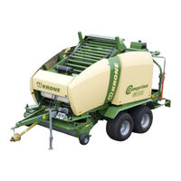
Krone Comprima CV 150 XC Original Operating Instructions (384 pages)
Brand:
Krone
| Category:
Lawn and Garden Equipment
| Size: 19 MB
Table of Contents
1 Foreword
3
2 Table of Contents
4
3 To this Document
11
Validity
11
Target Group of this Document
11
How to Use this Document
11
Identifying Symbols in the Operating Instructions
12
Identification of the Hazard Warnings
12
4 Safety
13
Purpose of Use
13
Intended Use
13
Basic Safety Instructions
14
Importance of the Operating Instructions
14
Personnel Qualification
14
Children in Danger
15
Connect the Machine to the Tractor
15
Structural Changes to the Machine
15
Additional Equipment and Spare Parts
15
Workstations and Passengers
15
Operational Safety: Technically Perfect Condition
16
Danger Zones
17
Keeping Safety Devices Functional
19
Personal Protective Equipment
19
Safety Signs on the Machine
20
Traffic Safety
20
Parking the Machine Safely
21
Consumables
21
Dangers Associated with the Operational Environment
21
Sources of Danger on the Machine
22
Dangers Associated with Certain Activities: Climbing up and down
23
Dangers Associated with Certain Activities: Work on the Machine
23
Dangers Associated with Certain Activities: Working on Wheels and Tyres
24
Behaviour in Hazardous Situations and When Accidents Occur
24
Safety Routines
25
Stopping and Securing the Machine
25
Supporting Lifted Machine and Machine Parts Securely
25
Coupling the Machine Safely
26
Uncoupling the Machine Safely
26
Preparing the Machine for Repair, Maintenance and Adjustment Work
27
Starting the Machine Safely
27
Position of the Adhesive Safety Stickers on the Machine
28
Introduction
28
Re-Ordering the Adhesive Safety and Information Labels
42
Affixing the Adhesive Safety and Information Labels
42
Contact
42
Safety Equipment
43
Parking Brake
44
Attaching the Safety Cable
45
Wheel Chocks
45
Secure the Machine against the Possibility of Rolling Back
46
Stop Points
46
Lifting Eyes
46
Raise
46
Parking Support
47
Lowering the Parking Support
47
Shut-Off Valve for Tailgate
48
Step for Working on the Linkage
49
Rollers on the Wrapping Table
50
Platform on the Wrapping Table
51
Identification Plate
52
Information Required for Questions and Orders
52
Technical Data
53
5 Commissioning
56
Before Initial Start-Up
57
Removing the Transport Holding down Tensioning Device
60
Changing the Drawbar Height and Adjusting the Hitch
62
PTO Shaft
65
Length Adjustment
65
Mounting the PTO Shaft on the Machine Side
66
Hose Holder Assembly
69
6 Start-Up
70
Mounting Onto the Tractor
71
Hydraulics
72
Special Safety Instructions
72
Connecting the Hydraulic Lines
73
Hydraulic Brake (Export)
76
Install the PTO Shaft
77
Compressed Air Connections for the Compressed Air Brake
79
Electrical Connections
80
Connecting the Terminal (on Tractors Without ISOBUS System)
81
Connecting the Terminal (on Tractors with Integrated ISOBUS System)
82
Using the Safety Chain
83
Net Brake
85
Running-In Period
85
Cam-Type Clutch Engaging
85
Wrapping Table
86
Using the Bale Cloth
87
Start-Up Bale Turner
88
Mounting the Stop / Holding Tube
89
Positioning the Bale Turner
90
Moving the Bale Turner into Working Position
91
Adjusting the Baffle Plate
91
Adjusting the Parking Jack
92
Moving the Bale Turner into Transport Position
93
Mounting the Bale Cloth on the Bale Turner
94
Removing the Bale Turner
94
7 Driving and Transport
95
Preparations for Road Travel
96
Lifting the Pick-Up
96
Checking Parking Support
97
Checking the Lighting System
97
Attaching the Bale Cloth
98
Parking
99
Securing the Machine against the Possibility of Rolling Back
99
Lowering the Parking Support
100
Disconnecting the PTO Shaft from the Tractor
100
Disconnecting the Supply Lines
101
8 KRONE ISOBUS Terminal
102
Installing the Terminal into Cabin
103
ISOBUS Short Cut Button
104
Connecting the Multi-Function Lever to the CCI Terminal (on Tractors with an Integrated ISOBUS System)
106
Connecting the Multi-Function Lever to the CCI Terminal (on Tractors Without ISOBUS System)107
107
Switching the Terminal on / off When the Machine Is Not Connected
108
Switching the Terminal on / off When the Machine Is Connected
109
Basic Screen
111
Adjustment of Bale Firmness (Display for Comprima CF 155 XC)
118
Adjustment of Target Bale Diameter (Display for Comprima CV150XC)
119
Adjusting the Target Bale Diameter (Display for Comprima CV 210 XC)
119
Messages
120
Menu Level
122
Short Overview
122
Calling up the Menu Level
125
Main Menu 1 Settings
126
Menu 1-2 Adjustment Baler
127
Menu 1-2-2 Bale Diameter (Only for Comprima CF155XC)
128
Menu 1-2-3 Number Net Winds
129
Menu 1-2-4 Sensitivity of the Direction Display (Only Comprima CF155)
130
Menu 1-2-5 Pre-Signalling
131
Menu 1-2-6 Filling Correction
132
Menu 1-2-9 Tying Start Delay
133
Menu 1-3 Adjustment Wrapper
134
Menu 1-3-1 Number of Layers
135
Menu 1-3-2 Number Slide Wrappings
136
Menu 1-3-3 Type of Operation Wrapper
137
Menu 1-3-4 Type of Operation Swivel Table
138
Menu 1-3-5 Sheet Width
139
Menu 1-3-6 Torn Sheet Control
140
Main Menu 2 Counters
142
Menu 2-1 Customer Counter
143
Menu 2-2 Total Bale Counter
145
Main Menu 3 Manual Operation
146
Menu 3-1 „Manual Operation Baler
147
Status Messages
148
Move Manually to Tying Position
150
Activating the Wrapping Table Manually (Only for Comprima CV150XC)
150
Drive Lifter Manually Upward/ Downward (Comprima CF155XC/CV210XC)
151
Opening/Closing the Bale Chamber
151
Move Swivel Table by Hand
152
Menu 3-2 Manual Operation Wrapper
152
Opening/Closing the Holding Arms
153
Switching On/Off Wrapping Arm
154
Move the Wrapping Arm to Zero Position
154
Menu 3-2 „Manual Operation Wrapping Arm" CV 210
155
Move the Height of the Wrapping Arms
156
Drive Height Wrapping Arm into Parking Position
157
Error Messages Manual Operation
159
Main Menu 4 Service
160
Menu 4-2 Manual Sensor Test
161
Actuator Test
171
Menu 4-4 Manual Actuator Test
171
Menu 4-8 Diagnostics
176
Menu 4-9 Manual Operation Without Confirmation Prompt
177
Main Menu 5 Information
179
Main Menu 6 Technician
179
Main Menu 7 ISOBUS
180
Menu 7-1 Virtual Terminal (VT)
181
Menu 7-1-1 Select Day/Night Display Lighting
182
Menu 7-1-3 „Softkeys ISO Terminal
183
Menu 7-1-4 Switch to Different Terminal
185
Menu 7-4 ISOBUS Diagnostics
186
Menu 7-4-2 Diagnostics Auxiliary Functions (AUX)
187
Messages
188
Query Message for Bale Chamber
188
Query Message Manual Operation
188
Prompt Message Repeat Wrapping
189
Alarm Messages
190
Acoustic Warnings
190
Note and Messages
191
Prompts
193
Physical Messages
194
General Messages
196
9 ISOBUS Operation
197
Mounting ISOBUS Terminal
198
Connection Terminal to Tractor
198
Connection Tractor to Machine
198
Differing Functions to KRONE ISOBUS Terminal CCI
199
ISOBUS „Auxiliary"-Function (AUX)
200
Example of Joystick Assignment for Fendt (Default Setting)
201
Recommended Settings for a WTK Multi-Function Lever (Default Setting)
202
10 Operation of the Hydraulic Zero Setting of Blades (Optional)
203
KRONE ISOBUS Terminal
204
Basic Screen in Case of a Connected Zero Setting of Blades (Option)
204
Sensor Test / Actuator Test
206
Alarm Messages for Blade Comfort Selection
207
Hydraulic System Circuit Diagrams
208
11 Operation
209
Adjustments before Starting Work
210
Travelling Speed
212
Filling the Bale Chamber
213
Reducing the Pressure on the Side Walls of the Bale Chamber
215
Assembly of Additional Tappet Strips on the Starter Roller
215
Assembly of Additional Ejector Plates in the Tailgate
216
Tying and Depositing Bales
219
Before Baling
219
Detaching the Bale Cloth
219
Tensioning the Floor Conveyor
220
After Baling
221
Releasing Tension on the Floor Conveyor
221
Overload Protection
222
Drive Chain for Pick-Up with Cam-Type Clutch
222
Pick-Up
223
Default Setting (Working Height Setting)
223
Bearing Pressure Relief of the Pick-Up
224
Roller Crop Guide
225
Adjusting the Baffle Plate
226
Cutting System
227
General Aspects
227
Cutting Length
228
Zero Position of the Cutter
231
Setting the Bale Diameter
235
Setting Baling Pressure
236
Net Wrapping
239
Net Wrapping Parts
239
Function of the Net Tying
239
Inserting Net Roll
240
Insert Net
241
Setting of the Feed Position
243
Setting of the Tying Position
244
Selecting the Number of Net Winds
244
Setting Cut-Off Position
245
Adjusting Soft Core
246
Blockage Due to Jammed Crop
249
Bale Wrapper
251
Special Safety Instructions
251
Components Bale Wrapper
252
Function Bale Wrapper
255
Store Bale
256
Inserting Sheet
257
Adjusting the Sheet Brake
262
Setting the Pre-Stretch of the Foil
263
Adjusting the Gearbox on the Swivel Table
264
Removing the Crop Blockages in the Crop Collection Area
265
Crop Blockage under the Cutting Rotor
266
Crop Blockage at Pick-Up
268
12 Settings
269
Setting the Net Brake
269
Releasing the Net Brake
270
Central Chain Lubrication System
271
13 Maintenance
275
Spare Parts
275
Maintenance Table
276
Setting of the Scraper Rail to the Upper Spiral Roller
277
Position of the Sensors
279
Adjusting the Sensors
283
Namur Sensor D = 12 MM
283
Namur Sensor D = 30 MM
283
Sensor Position Cutter Base (B8)
284
Checking and Setting Axial Play of the Net Brake
285
Tightening Torques
286
Tightening Torques (Countersunk Screws)
287
Tandem Axle
288
Setting of the Brakes with Hydraulic Linkage Setter
290
Tyres
291
Checking and Maintaining Tyres
292
Tyre Air Pressure
293
Drawbar
294
Hitches on the Drawbar
294
Oil Level Check and Oil Change on the Gearboxes
295
Oil Level Check and Oil Change Intervals (Gearboxes)
295
Filling Quantities and Lubrication Designations for Gearboxes
295
Main Drive
296
Slip-On Gear
297
Screw Connections at the Front and Rear of the Floor Conveyors
298
Novo Grip Belt on the Floor Conveyor
299
Checking the Safety Rollers of Single Blade Locking Device
300
Checks and Maintenance on Rear Floor Conveyor
301
Adjusting the Deflection Roller
302
Wrapping Table Chain
303
Drive Chains
304
Tensioning the Drive Chains
304
Front Floor Conveyor Drive
304
Rear Floor Conveyor Drive
305
Pick-Up
306
Conveyor Auger Drive
308
Roller Drive
308
Wrapping Arm Bearing
309
Hydraulics
311
Shut-Off Valve for Tailgate
312
On-Board Hydraulic System
313
Hydraulic Tank
315
Changing the Filter on the Hydraulic Tank
318
Replacing the Hydraulic Oil Filter
321
Electromagnetic Valves
323
Grinding Blades
324
Maintenance - Brake System (Special Equipment)
325
Coupling Heads (Non-Interchangeable)
326
Air Filter for Pipelines
327
Compressed-Air Reservoir
328
14 Maintenance - Lubrication
329
Lubricants
330
General Aspects
330
Lubricating the PTO Shaft
330
WALTERSCHEID Cam-Type Clutch K64/12 to K64/24, EK 64/22 to EK64/24
331
Lubrication Points
333
15 Placing in Storage
337
At the End of the Harvest Season
337
Before the Start of the New Season
338
Maintenance Work before the Beginning of the New Season
339
Venting the Overload Coupling on the PTO Shaft
340
16 Malfunctions - Causes and Remedies
341
General Malfunctions
342
Malfunctions on the Central Chain Lubrication System
345
Malfunctions on the Wrapping Mechanism
346
Error Messages of KRONE Operation Terminal
346
17 Disposal of the Machine
347
18 Appendix
348
Hydraulic System Circuit Diagrams
348
Electrical Circuit Diagram
354
19 Index
355
Advertisement
Advertisement
Related Products
Krone Comprima CF 155 XC
Krone Comprima CV 210 XC
Krone COMPRIMAF F 125
Krone COMPRIMAF F 125 XC
Krone COMPRIMAF F 155
Krone COMPRIMAF V 150
Krone COMPRIMAF V 180
Krone Comprima F 125
Krone Comprima F 155
Krone Comprima F 125 XC
Krone Categories
Farm Equipment
Lawn Mower
Lawn and Garden Equipment
Industrial Equipment
Utility Vehicle
More Krone Manuals
Login
Sign In
OR
Sign in with Facebook
Sign in with Google
Upload manual
Upload from disk
Upload from URL