Sign In
Upload
Manuals
Brands
Kromschroder Manuals
Control Systems
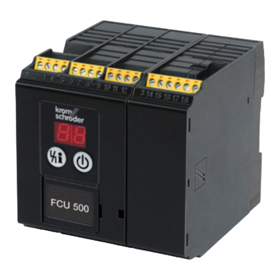
FCU 500
Kromschroder FCU 500 System Control Manuals
Manuals and User Guides for Kromschroder FCU 500 System Control. We have
1
Kromschroder FCU 500 System Control manual available for free PDF download: Technical Information
Kromschroder FCU 500 Technical Information (148 pages)
Protective system controls
Brand:
Kromschroder
| Category:
Control Systems
| Size: 7 MB
Table of Contents
Protective System Controls FCU 500, FCU 505
1
Contents
2
Table of Contents
2
1 Application
5
Application Examples
8
ON/OFF Rotary Impulse Control
8
Modulating Burner Control
10
Safety Limits (LDS) for Modulating Burner Control
11
Flame Control Using the Temperature
12
Furnace and Zone Control
13
2 Certification
14
3 Function
15
Connection Diagram
15
Fcu 500
15
Fcu 505
16
Assignment of Connection Terminals
17
Program Sequence
19
Fcu 500
19
Fcu 500
20
Fcu 505
21
Animation
22
4 Temperature Monitoring
23
High Temperature Operation with Safety Temperature Monitor Function (STM Function)
24
With Integrated STM
24
With External STM
25
With Integrated and External STM
25
Maximum Temperature Monitoring with (Flue Gas) Safety Temperature Limiter
26
Function)
26
With Integrated STL/FSTL
26
With External STL/FSTL
26
5 Air Control
27
Controlled Air Flow
28
Capacity Control
29
6 Furnace Zone Control
31
7 Valve Proving System
33
Tightness Control
34
Test Instant
35
One Test Volume between 2 Gas Solenoid Valves
36
One Test Volume for System Tightness
39
Two Test Volumes for System Tightness
42
Large Test Volumes with Reduced Testing Time
46
Test Period T
48
For One Test Volume
48
Valves
48
P1 between 2 Gas Solenoid
48
For One Test Volume V for System Tightness
48
For Two Test Volumes for System Tightness
49
Extended Valve Opening Time 1 T
50
Measurement Time T
53
Proof of Closure Function
57
8 Bcsoft
58
9 Fieldbus Communication Via Ethernet
59
FCU and Bus Module BCM
60
Configuration, Planning
61
Profinet/Device Master Data File (GSD)
61
Modbus TCP
61
Modules/Registers for Process Data
62
Device Parameters and Statistics
68
10 Program Step/Status
69
11 Fault Signalling
70
12 Parameters
74
Scanning the Parameters
79
Safety Limits
79
Emergency Stop
79
High Gas Pressure Protection
80
Low Gas Pressure Protection
80
Low Air Pressure Protection
81
Safety Time During Operation T SB
81
High Temperature Operation
82
Temperature Monitoring Mode
82
Thermocouple
83
Temperature Difference Limit Value
83
STM Limit Value (High Temperature Operation)
84
STL/FSTL Limit Value (System Protection)
84
Temperature Hysteresis
85
Pre-Purge During High Temperature Operation
86
Air Control
87
Fan in the Event of Fault
87
Fan Run-Up Time T GV
87
Fan Ready for Operation
87
Air Monitoring During Controlled Air Flow
88
Pre-Purge Time T PV
88
Air Flow Monitoring During Pre-Purge
89
Post-Purge Time T
89
Air Flow Monitoring During Post-Purge
90
Capacity Control
91
Running Time Selection
100
Running Time
100
Controller Enable Signal Delay Time T RF
101
Minimum Enable Time
101
Burner Operating Signal
101
Controller Enable Time Limit
102
Capacity Control (Bus)
103
Valve Check
108
Valve Proving System
108
Relief Valve (VPS)
108
Tightness Control Test Volume
109
Pressure Reduction
110
Opening Time Relief Valve V3
110
Measurement Time
110
Valve Opening Time 1 T
112
Valve Opening Time 2 T
112
And V
112
Behaviour During Start-Up
113
Minimum Pause Time T
113
Switch-On Delay Time T MP E
113
Filling Time before Start-Up
113
Manual Mode
114
Operating Time in Manual Mode
114
Functions of Terminals 51, 65, 66, 67 and
115
Function of Terminal 51
115
Function of Terminal 65
116
Function of Terminal 66
116
Function of Terminal 67
117
Function of Terminal 68
117
Password
118
Fieldbus Communication
118
13 Selection
119
Type Code
119
14 Project Planning Information
120
Installation
120
Commissioning
120
Electrical Connection
121
Ocu
121
Safety Current Inputs
122
High Temperature Operation
123
Safety Temperature Monitor (STM)
123
Safety Temperature Limiter (STL)
124
Temperature Sensors (Double Thermocouples)
124
Thermocouples
124
Pfhd
126
And Thermocouple
126
Safety Interlock Output
127
Safety Interlock Output in the Case of Higher
127
Power Requirement
127
BCU with Power Supply for Valves and Ignition Transformer Via Safety Interlocks
128
Actuators
129
IC 20
129
Air Control
129
Parameter Chip Card
130
System Leak Tightness Check
130
15 Accessories
131
Bcsoft
131
Opto-Adapter PCO 200
131
Bluetooth Adapter PCO 300
131
Ocu
131
Connection Plug Set
132
Stickers for Labelling
132
Changed Parameters" Stickers
132
16 Ocu
133
Application
133
Function
134
Manual Mode
135
Electrical Connection
135
Installation
136
Selection
136
Technical Data for OCU
136
17 Bcm 500
137
Application
137
Function
137
Electrical Connection
137
Installation
138
Selection
138
Technical Data
138
18 Technical Data
139
Electrical Data
139
Mechanical Data
140
Environment
140
Fcu
140
Dimensions
140
Safety-Specific Characteristic Values
141
Converting Units
142
19 Maintenance
143
20 Legend
144
21 Glossary
145
Safety Shut-Down
145
Fault Lock-Out
145
Warning Signal
145
Timeout
146
Lifting
146
Diagnostic Coverage DC
146
Operating Mode
146
Safe Failure Fraction SFF
147
Probability of Dangerous Failure PFHD
147
Mean Time to Dangerous Failure MTTF D
147
Feedback
148
Contact
148
Advertisement
Advertisement
Related Products
Kromschroder FCU 505
Kromschroder BGT SA-8U/1DP
Kromschroder BGT SA-9U/1DP
Kromschroder BGT Series
Kromschroder PFA 700
Kromschroder PFA 710
Kromschroder PFA Series
Kromschroder Categories
Control Unit
Control Systems
Controller
Burner
Thermostat
More Kromschroder Manuals
Login
Sign In
OR
Sign in with Facebook
Sign in with Google
Upload manual
Upload from disk
Upload from URL