Sign In
Upload
Manuals
Brands
Kramer Manuals
Matrix Switcher
VP-773A
Kramer VP-773A Manuals
Manuals and User Guides for Kramer VP-773A. We have
1
Kramer VP-773A manual available for free PDF download: User Manual
Kramer VP-773A User Manual (119 pages)
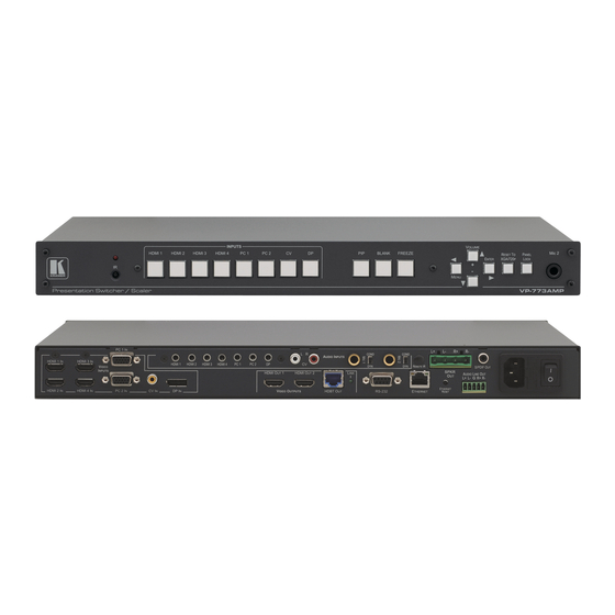
Switcher/Scaler
Brand:
Kramer
| Category:
Switch
| Size: 5 MB
Table of Contents
User Manual
1
Table of Contents
4
1 Introduction
7
2 Getting Started
8
Achieving the Best Performance
8
Safety Instructions
8
Recycling Kramer Products
9
3 Overview
10
HDCP Compliance
13
About Hdbaset™ Technology
13
Using Twisted Pair Cable
13
Defining the VP-773A Presentation Switcher/Scaler
13
Figure 1: VP-773A Presentation Switcher/Scaler Front Panel
14
Figure 2: VP-773A Presentation Switcher/Scaler Rear Panel
15
4 Installing in a Rack
17
5 Connecting the VP-773A
18
Figure 3: 15-Pin HD Connector Pinout
18
Figure 4: Connecting the VP-773A Presentation Switcher/Scaler
20
Wiring the RJ-45 Connectors
21
Figure 5: TP PINOUT
21
Connecting the Balanced Stereo Audio Output
22
Microphone Pinout
22
Audio Input Pinout
22
Figure 6: Connecting the Balanced Stereo Audio Output
22
Figure 7: Connecting an Unbalanced Stereo Audio Acceptor to the Balanced Output
22
Figure 8: Microphone Pinout
22
Figure 9: Audio Input Pinout
22
6 The OSD Menu
23
OSD Menu Operation Example
23
The Input Menu
26
Figure 10: Input Menu
26
Figure 11: Select the Display Mode
28
Figure 12: Changing the Size of the Window
29
Figure 13: Increasing the Width
30
Figure 14: Increasing the Height
30
Figure 15: Positioning the Window
31
Figure 16: Window Customization
31
Figure 17: H-Position Slide Bar
32
Figure 18: Moving the Pip Window
32
The Audio Menu
33
Figure 19: Audio Menu
33
Figure 20: Set the Output Volume Level
34
The Process Menu
35
Figure 21: Process Menu
35
The Picture Menu
36
Figure 22: Picture Menu
36
The Enhance Menu
37
Figure 23: Enhance Menu
37
The Scale Menu
38
Figure 24: Scale Menu
38
The Miscellaneous Menu
41
Figure 25: Misc Menu
41
Figure 26: XML File Transfer
45
Figure 27: Emergency Alert System Display
45
7 The Display Modes
47
The Single Window Display Mode
47
The Dual Window Display Mode
47
Figure 28: CV Superimposed over DP
50
8 Controlling the VP-773A
52
Controlling Via the Front Panel Buttons
52
Controlling Via the OSD Menu
52
Controlling Via the VP-773A Web Pages
53
Figure 29: Entering the IP Number in the Address Bar
53
Figure 30: Local Area Connection Properties Window
55
Figure 31: Internet Protocol Version 4 Properties Window
56
Figure 32: Internet Protocol Version 6 Properties Window
56
Figure 33: Internet Protocol Properties Window
57
Controlling Via the Infrared Remote Control Transmitter
58
Figure 34: Infrared Remote Control Transmitter
58
9 Using the Embedded Web Pages
60
Figure 35: the Authentication Window
60
Figure 36: the Loading Page
61
The Routing and Scaling Page
62
Figure 37: the Routing & Scaling Page with Web Page List on the Left
62
Figure 40: the Routing & Scaling Page - Moving the PIP Window
63
Figure 41: the Routing & Scaling Page - PIP Window
64
Figure 42: the Routing & Scaling Page - Changing the Resolution
65
Figure 43: the Routing & Scaling Page - the Swap Inputs
66
Figure 44: the Routing & Scaling Page - Swapping the Inputs
66
Figure 45: the Routing & Scaling Page - Auto Switching Window (Main Tab)
67
Figure 46: the Routing & Scaling Page - Selecting the Inputs to Scan (Pip Tab)
67
Figure 47: the Routing & Scaling Page - Auto Switching Window
68
Figure 48: the Routing & Scaling Page - Lower Buttons Bar
68
Figure 49: the Routing & Scaling Page - Selecting a Preset
70
Figure 50: the Routing & Scaling Page - Saving the Selected Preset
70
Figure 51: the Routing & Scaling Page - Recalling a Preset
70
Figure 52: the Routing & Scaling Page - TAKE Mode
71
Figure 53: the Routing & Scaling Page - Cancel the Changes
71
The Device Settings Page
72
Figure 54: the Routing & Scaling Page - Audio Level Sliders
72
Figure 55: the Routing & Scaling Page - Muting the Audio Level
72
Figure 56: the Device Settings Page
72
Figure 57: the Device Settings Page - Changing the IP Number
73
Figure 58: the Device Settings Page - Selecting the Firmware File
73
Figure 59: the Device Settings Page - Firmware File Downloaded
74
Figure 60: the Device Settings Page - Firmware Upgrade Warning
74
Figure 61: the Device Settings Page - Firmware Upgrade Stage
74
Figure 62: the Device Settings Page - Writing the Firmware
75
Figure 63: the Device Settings Page - Firmware Upgrade Waiting for Restart
75
Figure 64: the Device Settings Page - the Reset Device Window
76
Figure 65: the Device Settings Page - the Reset Device Window Including Ethernet
76
Figure 66: the Device Settings Page - Web Page Reset
77
Figure 67: the Device Settings Page - the Information Window
78
The Input Settings Page
79
Figure 68: the Input Settings Page
79
Figure 69: the Input Settings Page - PIP Window Inactive
80
The Enhance Page
82
Figure 70: the Enhance Page
82
The Output Settings
83
Figure 71: the Output Settings Page
83
The Audio Settings Page
84
Figure 72: the Audio Settings Page - General Tab
84
Figure 73: the Audio Settings Page - Microphones Tab
85
Figure 74: the Audio Settings Page - Microphones Tab
85
Figure 75: the Audio Settings Page - Setting the MIX Level
86
Figure 76: the Audio Settings Page - Output Volume Pre-Limiter
86
The RS-232 over TP Page
88
Figure 77: the RS-232 over TP Page
88
Figure 78: the RS-232 over TP Page - the Remote Device Commands Table
89
Figure 79: the RS-232 over TP Page - the Edit Command Window
89
Figure 80: the RS-232 over TP Page - Setting the Trigger
90
Figure 81: the RS-232 over TP Page - Setting the Sync on Trigger
90
Figure 82: the RS-232 over TP Page - the Power on Command
91
The Emergency Alert System Page
92
Figure 83: the Emergency Alert System Page
92
Figure 84: the Emergency Alert System Page - Local Message Example
93
The Security Page
94
Figure 85: the Security Page - Security Deactivated
94
Figure 86: the Security Page - Activating the Security
94
Figure 87: the Security Page - Authentication Required
94
The about Us Page
95
Figure 88: the Security Page
95
Figure 89: the about Us Page
95
Save or Upload a Configuration
96
Figure 90: Loading a Configuration
96
Figure 91: Saving a Configuration
96
10 Port Tunneling
97
Figure 92: Port Tunneling
97
11 Flash Memory Upgrade
99
12 Technical Specifications
100
Default Communication Parameters
101
Input Resolutions
101
Output Resolutions
102
13 The VP-773A RS-232 Communication Protocol
103
Using the Communication Protocol
103
Communication Protocol: Mimicking OSD
103
Protocol Table: Mimicking Remote and Front Panel Buttons
113
The Protocol 3000 Common Operation Commands
114
Safety Warning
119
Advertisement
Advertisement
Related Products
Kramer VP-729
Kramer VP-727XL
Kramer VP-725DS
Kramer VP-747
Kramer VP-727
Kramer VP-720DS
Kramer VP-723DS
Kramer VP-719DS
Kramer VP-772
Kramer VP-778
Kramer Categories
Matrix Switcher
Switch
Media Converter
Amplifier
Receiver
More Kramer Manuals
Login
Sign In
OR
Sign in with Facebook
Sign in with Google
Upload manual
Upload from disk
Upload from URL