Sign In
Upload
Manuals
Brands
Kontron Manuals
Switch
AM4904
Kontron AM4904 Manuals
Manuals and User Guides for Kontron AM4904. We have
1
Kontron AM4904 manual available for free PDF download: User Manual
Kontron AM4904 User Manual (135 pages)
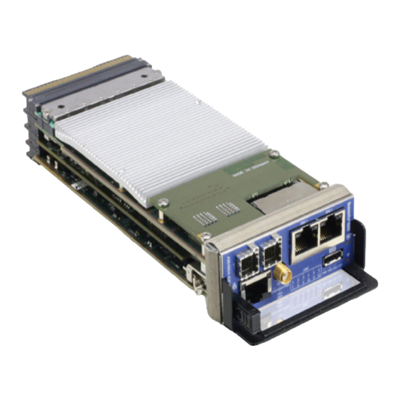
MicroTCA Carrier Hub
Brand:
Kontron
| Category:
Switch
| Size: 6 MB
Table of Contents
Revision History
2
Customer Service
2
Table of Contents
3
List of Tables
7
List of Figures
9
Proprietary Note
10
Trademarks
10
Environmental Protection Statement
10
Before You Begin
11
When Working Inside a Computer
12
Advisory Conventions
13
Safety Instructions
14
Special Handling and Unpacking Instructions
15
General Instructions on Usage
16
Regulatory Compliance Statements
17
Two Year Warranty
18
1 Introduction
20
Microtca™ System Overview
20
Product Overview
20
Optional Accessories
20
Technical Specifications
21
General
21
ATCA Leds
21
Operating Voltages
21
Operation Power
21
Temperature
21
Humidity
21
Altitude
22
Vibration
22
Shock
22
Safety
22
Electromagnetic Compatibility
22
Mtbf
23
Standards Compliance
23
Related Publications
23
Table 1-1: Related Publications
23
2 Functional Description
25
Block Diagrams
25
Microtca Carrier Management Controller
26
Unit Computer Powerpc 405EX
26
DDR2 Memory
26
NOR Flash
27
NAND Flash
27
Dual GE PHY
27
Fpga
27
I2C Eeprom
28
Real Time Clock (RTC)
28
Serial Interface
28
FE Management
28
Board Sensors
28
Table 2-1: Sensor List AM4904-Base
29
Table 2-2: Sensor List AM4904-Pcie
30
Table 2-3: Sensor List AM4904-Srio
31
Table 2-4: AM4904 Temperature Sensor Thresholds [°C]
32
Table 2-5: AM4904 Voltage Sensor Thresholds
32
Table 2-6: Sensor Type Codes and Event Offsets
33
Managed Ethernet Switch
34
Fabric [A] Switch
34
Table 2-7: FASTPATH AM4904 Switch Port Mapping
34
Switch Management Software
35
PCI Express / Serial Rapidio Switch
39
Figure 2-2: Pcie Fabric
39
Table 2-8: AM4904-Pcie Switch Port Mapping
40
Figure 2-3: Srio Fabric
40
Clocking
41
Pcie Clock Distribution
41
Telco Clock Distribution
41
Board Interfaces
42
Figure 2-4: AM4904-Base Front Panel Leds and Interfaces
43
Figure 2-5: AM4904-Pcie Front Panel Leds and Interfaces
43
Module Management Leds
44
MCH/AMC Status Leds
45
Table 2-10: Module Management Leds Function
45
Synchronisation Clock Leds
46
Table 2-11: AMC and Other MCH Leds
46
Table 2-12: Synchronisation Cock Leds
46
Figure 2-7: Module Handle Positions
47
Module Handle Positions
47
Power Module and Cooling Unit Status Leds
47
Table 2-13: PLL Status
47
Table 2-14: MCH LED Status
47
Serial Port
48
Table 2-16: Serial Port Pinout
48
Management Ethernet Interface (10/100/1000Base-T)
49
Table 2-17: Management RJ45 Connector Pin Assignment
49
Table 2-18: Management Leds Signification
49
Uplink Ethernet Ports
49
Srio Densishield™ Interfaces
50
Table 2-19: Gbe Connector
50
Table 2-20: Ethernet LED Status
50
Table 2-21: Srio Connections
50
Figure 2-8: Densishield™ Uplink Cable Connector Face (Front Connector Is Mirrored)
51
Table 2-22: Densishield™ Uplink Connector Pinout
51
MCH Interconnection
52
Table 2-23: Densishield™ to Infiniband Adapter Wiring
52
Fabric Interface
53
Inter-MCH IPMB-L Interface
53
IPMB-0 Interface
53
IPMB-L Interface
53
JTAG Interface
53
MCH Update Channel Interface
53
Pinout of MCH Card-Edge Connectors
53
Table 2-24: MCH Card-Edge Tongue 1 Connectors Pinout
53
Table 2-25: MCH Card-Edge Tongue 2 (Clocking) Connectors Pinout
56
Table 2-26: MCH Card-Edge Tongue 3 (Pcie Fabric) Connectors Pinout
58
Table 2-27: MCH Card-Edge Tongue 3 (Srio Fabric) Connectors Pinout
62
Table 2-28: MCH Card-Edge Tongue 4 Connectors Pinout
62
3 Operating the Unit
66
Board Access
66
Table 3-1: Management Interfaces
66
MCMC/CM Application
67
CM Configuration Options
67
Table 3-2: Configuration File Precedence
67
CM Modules
68
Table 3-3: Available Modules
68
CM Command Line Interface (CLI)
69
Accessing MCMC: Clicm
69
CM Commands
69
Table 3-4: CLI CM Commands
69
Counter Commands
70
Ekeying Commands
70
Fan Commands
70
Fru Commands
71
IPMB Commands
71
Boot Option Commands
71
I2C Commands
72
LAN Commands
72
Log Commands
72
Table 3-11: CLI I2C Commands
72
Table 3-12: CLI LAN Commands
72
Table 3-13: CLI Log Commands
72
MC Commands
73
Memory Commands
73
Monitor Commands
73
Table 3-14: CLI MC Commands
73
MP Commands
74
Pcie Commands
74
Table 3-17: CLI MP Commands
74
Table 3-18: CLI Pcie Commands
74
PM Commands
75
Redundancy Commands
75
SEL Commands
75
Sensor Commands
75
Table 3-19: CLI PM Commands
75
Table 3-20: CLI RM Commands
75
Table 3-21: CLI SEL Commands
75
SRIO Commands
76
Clock Commands
76
Table 3-22: CLI Sensor Commands
76
Table 3-23: CLI Srio Commands
76
Table 3-24: CLI Clock Commands
76
Miscellaneous Commands
77
System Configuration Tools
77
Accessing the PLD: Pldtool
77
Accessing Switch Management: Fpcli
77
Table 3-25: CLI Miscellaneous Commands
77
Accessing MCMC: Ipmitool
78
Configuring Services: Chkconfig
79
Configuring PCI Express
80
Table 3-26: PCI Express Settings
81
Configuring Srio
82
Table 3-27: SRIO Settings
82
Clocking Configuration
83
Table 3-28: PLL Settings
84
Table 3-29: Command Output
87
MCH Redundancy Support
88
Cooling Unit Management
88
Table 3-30: FAN Control States
89
Ipmi
90
Supported IPMI Commands
90
Table 3-31: IPMI Device Commands
90
Table 3-32: PICMG Commands
94
Table 3-34: Microtca.0 Commands
95
Table 3-35: Kontron Specific OEM Commands
95
Table 3-33: AMC.0 Commands
95
Board FRU Information
97
Bootloader
98
Power on Self Test
98
Table 3-36: POST Routines and Error Codes
98
Bootloader Shell and Options
99
Table 3-37: Bootloader Environment Variables
99
Firmware Administration
100
Table 3-38: FLASH Partition Scheme (64MB)
100
Updating Firmware
101
4 Hardware Installation
104
Safety Requirements
105
Hot Swap Procedures
106
Hot Swap Insertion
106
Hot Swap Extraction
106
5 Power Considerations
109
AM4904 Input Voltage Ranges
110
Carrier Power Requirements
110
Payload Power
110
Management Power
110
Payload and Management Voltage Ramp
110
Payload Power Consumption
110
Table 5-1: DC Operational Input Voltage Ranges
110
Power Consumption
111
Management Power Consumption
111
Table 5-2: Payload Power Consumption
111
Payload Start-Up Current of the AM4904
112
6 Thermal Considerations
113
Thermal Monitoring
114
Figure 6-1: Temperature Sensor Locations AM4904 (Base Variant, Top View)
114
Figure 6-2: Temperature Sensor Locations AM4904 (Base Variant, Bottom View)
115
Figure 6-3: Temperature Sensor Locations AM4904 (Pcie Variant, Bottom View)
115
Table 6-1: MCMC Temperature Sensors Thresholds
116
Figure 6-4: Temperature Sensor Locations AM4904 (Srio Variant, Top View)
116
Thermal Regulation
117
Figure 6-5: Maximum Ambient and Inlet Temperature Versus Airflow
117
Airflow
118
Figure 6-6: Impedance Curve AM4904-Base
118
Figure 6-7: Impedance Curve AM4904-Pcie
118
Figure 6-8: Impedance Curve AM4904-Srio
119
Figure 6-9: Airflow Distribution AM4904-Base
119
Table 6-2: Airflow Values
120
Figure 6-10: Airflow Distribution AM4904-Pcie
120
Figure 6-11: Airflow Distribution AM4904-Srio
120
A Configuration Options
122
Table A-1: CM Configuration File Settings
122
Getting Help
128
Returning Defective Merchandise
129
When Returning a Unit
130
C Glossary
132
Advertisement
Advertisement
Related Products
Kontron MicroTCA AM5901
Kontron AM4301
Kontron AM4500
Kontron AM4100
Kontron AM4150
Kontron AM4011
Kontron AdvancedTCA AM4330
Kontron AM4520
Kontron AdvancedMC AM4211
Kontron AM4024
Kontron Categories
Computer Hardware
Motherboard
Server
Industrial PC
Desktop
More Kontron Manuals
Login
Sign In
OR
Sign in with Facebook
Sign in with Google
Upload manual
Upload from disk
Upload from URL