Sign In
Upload
Manuals
Brands
Kohler Manuals
Crankshaft
Command PRO ECH630
Kohler Command PRO ECH630 Manuals
Manuals and User Guides for Kohler Command PRO ECH630. We have
5
Kohler Command PRO ECH630 manuals available for free PDF download: Service Manual, Owner's Manual
Kohler Command PRO ECH630 Service Manual (141 pages)
Brand:
Kohler
| Category:
Engine
| Size: 11.51 MB
Table of Contents
Contents
1
Safety Precautions
2
Maintenance Instructions
3
Maintenance Schedule
3
Repairs/Service Parts
3
Oil Recommendations
4
Fuel Recommendations
4
Storage
4
Specifications
5
Engine Dimensions with Heavy-Duty Air Cleaner-Flywheel Side
5
Engine Dimensions with Heavy-Duty Air Cleaner-Oil Filter Side
6
Engine Dimensions with Heavy-Duty Air Cleaner-PTO Side
7
Engine Dimensions with Heavy-Duty Air Cleaner-Starter Side
8
Engine Dimensions with Low-Profi Le Air Cleaner-Flywheel Side
9
Engine Dimensions with Low-Profi Le Air Cleaner-Oil Filter Side
10
Engine Dimensions with Low-Profi Le Air Cleaner-PTO Side
11
Engine Dimensions with Low-Profi Le Air Cleaner-Starter Side
12
Engine Identification Numbers
13
General Specifications
13
Torque Specifications
13
Clearance Specifications
16
General Torque Values
21
Metric Fastener Torque Recommendations for Standard Applications
21
Separate Tool Supplies
22
Tools
22
Aids
23
Flywheel Holding Tool
24
Rocker Arm/Crankshaft Tool
24
Troubleshooting Guide
25
External Engine Inspection
26
Cleaning Engine
26
Crankcase Vacuum Test
27
Compression Test
28
Cylinder Leakdown Test
28
Low-Profile Air Cleaner
29
Heavy-Duty Air Cleaner
29
Breather Tube
29
Air Cooling
29
EFI System
30
Fuel Line
30
Operation
30
Crankshaft Position Sensor Bracket
31
Important Notes
33
Electrical Components
34
Electronic Control Unit (ECU)
34
Pinout of ECU
34
ECU Reset Procedure
35
TPS Learn Procedure
35
Wiring Harness
36
EFI Wiring Diagram 6-Terminal Connector (Engines with Separate MAP Sensor and Intake Air Temperature Sensor)
36
EFI Wiring Diagram 5-Terminal Connector and Optional Key Switch (Engines with Separate MAP Sensor and Intake Air Temperature Sensor)
37
EFI Wiring Diagram 6-Terminal Connector (Engines with Separate MAP Sensor)
38
EFI Wiring Diagram 5-Terminal Connector and Optional Key Switch (Engines with TMAP Sensor)
39
Crankshaft Position Sensor
40
Throttle Position Sensor (TPS)
40
Contacting (Brush) Type TPS Resistance Table
40
Replace Magnet Assembly
41
Contactless (Magnet) Type TPS
41
Engine (Oil) Temperature Sensor
42
Intake Air Temperature Sensor
42
Manifold Absolute Pressure Sensor (MAP)
42
Temperature/Manifold Absolute Pressure (TMAP) Sensor
42
Oxygen Sensor Components
43
Cutaway Oxygen Sensor Components
43
Sensor Signal Observation
44
Removal Inspection
44
Troublshooting-Oxygen Sensor
45
Fuel Injectors
46
Fuel Components
47
Ignition Coil
47
Fuel Pump Module (FPM)
47
High Pressure Fuel Line
48
Purge Port and Vent Hose Assembly
48
Throttle Body/Intake Manifold Assembly
48
Function Test
50
Fault Codes
50
Example of Diagnostic Display
50
Diagnostic Fault Code Summary
50
Diagnostic Code Summary
51
Troubleshooting Flow Chart
57
EFI Diagnostic Flow Diagram
58
Bosch EFI System
59
Initial Starting/Priming Procedure
62
Speed Sensor Circuit
63
TPS Initialization Procedure
64
Cutaway of Oxygen Sensor
66
To Replace Oxygen Sensor
67
Fuel Injector Details
68
Injector Inspection Points
69
Fuel Pump
70
Fuel Pressure Regulator Details
70
Fuel Rail
71
Idle Speed Adjustment (RPM)
71
Idle Speed Screw Dampening Spring
71
Initial Governor Adjustment
71
“35 Pin” (MA 1.7) Metal-Cased ECU Systems
74
“24 Pin” (MSE 1.0) Plastic-Cased ECU Systems
76
“32 Pin” (MSE 1.1) Plastic-Cased ECU Systems
78
Fuel System
80
Flow Chart Diagnostic Aids
89
Bosch EFI Diagnostic Flow Diagram
91
Lubrication System
92
Lubrication Components
92
Check Oil Level
92
Change Oil and Filter
93
Oil Cooler
93
Oil Sentry
93
Spark Plug Component and Details
94
Service
94
Electrical System
94
Battery Size Recommendations
95
Battery Maintenance
95
Battery Test
95
Battery Charging System
96
Fuse Replacement
98
Starter System
99
Solenoid Shift Starter Components
100
Starter Disassembly
100
Brushes and Springs Detail
100
Armature Components and Details
101
Brush Replacement
101
Starter Reassembly
101
Solenoid Tests
102
Disassembly/Inspection and Service
103
External Engine Components
103
Disconnect Spark Plug Leads
104
Drain Oil from Crankcase and Remove Oil Filter
104
Remove Oil Cooler
104
Remove Muffler
104
External Governor Control (ECH EFI)
105
Remove External Governor Controls
105
Remove Lift Fuel Pump and Fuel Pump Module
106
Remove Fuel Pump Module (ECH EFI)
107
Remove Electronic Control Unit (ECU)
107
Remove Electronic Control Unit Bracket and Electric Starter Motor
107
Throttle Body Components
107
Remove Debris Screen Guard
108
Remove Debris Screen
108
Remove Outer Baffles and Blower Housing
108
Remove Oil Sentry
108
Remove Inner Baffles and Breather Cover
109
Intake Manifold Components (ECH EFI)
109
Remove Crankshaft Position Sensor
109
Remove Manifold Absolute Pressure (MAP) Sensor or Temperature/Manifold Absolute Pressure (TMAP) Sensor (ECH EFI)
109
Cylinder Head Components
110
Remove Valve Covers (ECH EFI)
110
Remove Cylinder Heads and Hydraulic Lifters
110
Disassemble Cylinder Heads
111
Valve Details
112
Valve Guides
112
Valve Seat Inserts
113
Lapping Valves
113
Flywheel Components
113
Remove Fan and Flywheel
113
Remove Stator and Backing Plate (ECH EFI)
114
Remove Closure Plate Assembly
114
Governor Shaft Press Depth Details
114
Oil Pump Assembly
115
Crankcase Components
116
Remove Camshaft
116
Remove Governor Cross Shaft
116
Governor Cross Shaft Oil Seal
117
Remove Connecting Rods with Pistons and Rings
117
Piston and Rings Components and Details
117
Install New Piston Rings
118
Piston Ring Orientation
118
Connecting Rods
119
Crankshaft Components and Details
119
Crankcase Inspection and Service
120
Honing Detail
120
Clean Cylinder Bore after Honing
120
Measuring Piston-To-Bore Clearance
121
Piston Detail
121
Install Flywheel End Oil Seal
123
Oil Seal Detail
123
Install Crankshaft
123
Install Connecting Rods with Pistons and Rings
123
Governor Gear Assembly
124
Thrust Bearing, Washer and Shim
124
Install Closure Plate Oil Seal
124
Oil Seal Details
124
Install Closure Plate Assembly
125
Closure Plate Fastener Torque Sequence
125
Install Stator and Backing Plate
125
Install Flywheel
126
Install Fan
126
Install Hydraulic Lifters
127
Valve Stem Seals
128
Assemble Cylinder Heads
128
Install Cylinder Heads
128
Install Push Rods and Rocker Arms
128
Install Intake Manifold
129
Install Fuel Injectors
129
Install Oil Temperature Sensor (ECH EFI)
131
Install Oil Sentry
131
Install Blower Housing and Outer Baffles
132
Install Rectifier-Regulator
132
Install Metal Debris Screen
132
Install Plastic Debris Screen
133
Install Electric Starter Motor and ECU Bracket (ECH EFI)
133
Install Electronic Control Unit (ECU)
133
Install Lift Fuel Pump and Fuel Pump Module
134
Install External Governor Control (ECH EFI)
135
Install Throttle Control Panel
137
Install Air Cleaner Assembly
137
Setting Initial Governor Adjustment
137
Install Muffler
137
Sensitivity Adjustment
138
Testing Engine
138
Advertisement
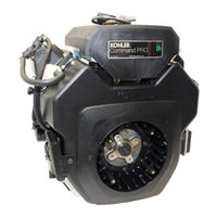
Kohler Command PRO ECH630 Service Manual (154 pages)
Command PRO HORIZONTAL CRANKSHAFT
Brand:
Kohler
| Category:
Crankshaft
| Size: 10.71 MB
Table of Contents
Table of Contents
3
Section 1. Safety and General Information
5
Section 2. Tools & Aids
21
Section 3. Troubleshooting
21
Section 4. Air Cleaner and Air Intake System
29
System
33
Description
34
Fuel Pump Module Connector Removal
34
Fuel Recommendations
34
EFI Fuel System Components
35
Operation
35
Important Service Notes
35
Electronic Control Unit (ECU)
35
Crankshaft Position Sensor
35
Engine (Oil) Temperature Sensor
35
Intake Air Temperature Sensor
35
Oxygen Sensor
35
Initial Starting/Priming Procedure
34
Electrical Components
35
Section 5. Electronic Fuel Injection (EFI) System
35
Manifold Absolute Pressure (MAP) Sensor
48
Fuel Injectors
48
Ignition System
51
Spark Plugs
52
Battery Charging System
52
Fuel Components Fuel Pump
52
Fuel Filter
54
High Pressure Fuel Line
54
Purge Port and Vent Hose Assembly
55
Throttle Body/Intake Manifold Assembly
55
Idle Speed Adjustment (RPM)
55
Initial Governor Adjustment
56
Troubleshooting
58
Troubleshooting Guide
58
Fuel System
58
Fault Codes
59
Troubleshooting Flow Chart
67
Flow Chart Diagnostic Aids
69
Section 6. Lubrication System
71
Section 7. Electrical System and Components
77
Section 8. Disassembly
80
Section 9. Inspection and Reconditioning
113
Section 10. Reassembly
124
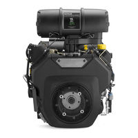
Kohler Command PRO ECH630 Service Manual (124 pages)
Horizontal crankshaft
Brand:
Kohler
| Category:
Crankshaft
| Size: 7.77 MB
Table of Contents
Specifications
5
Troubleshooting
18
Lubrication System
81
Electrical System
83
Advertisement
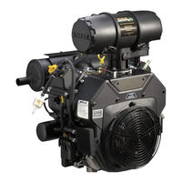
Kohler Command PRO ECH630 Owner's Manual (17 pages)
Horizontal Crankshaft
Brand:
Kohler
| Category:
Crankshaft
| Size: 3.31 MB
Table of Contents
California Proposition 65 Warning
3
Safety Precautions
4
Oil Recommendations
5
Fuel Recommendations
5
Check Oil Level
6
Check Air Cleaner
6
Pre-Start Checklist
6
Maintenance Instructions
8
Maintenance Schedule
8
Oil Disposal
8
Change Oil Filter
9
Air Cleaner Service
9
Battery Charging
10
Jump Starting
10
Troubleshooting
11
Fuse Replacement
12
Wire Color
12
Fuse Rating
12
Parts Ordering
13
Engine Identification
13
Specifications
14
Kohler Command PRO ECH630 Owner's Manual (8 pages)
Horizontal/Vertical crankshaft
Brand:
Kohler
| Category:
Crankshaft
| Size: 1.39 MB
Advertisement
Related Products
Kohler Command PRO Command PRO ECH680
Kohler Command PRO ECH730
Kohler Command PRO ECH650
Kohler Command PRO ECH740
Kohler Command PRO ECH749
Kohler Command PRO ECV650
Kohler Command PRO ECV680
Kohler Command PRO ECV730
Kohler Command PRO ECV749
Kohler Command PRO ECV630
Kohler Categories
Plumbing Product
Bathroom Fixtures
Bathtubs
Toilets
Engine
More Kohler Manuals
Login
Sign In
OR
Sign in with Facebook
Sign in with Google
Upload manual
Upload from disk
Upload from URL