Sign In
Upload
Manuals
Brands
Koden Manuals
Marine Radar
MDC-5500 SERIES
Koden MDC-5500 SERIES Manuals
Manuals and User Guides for Koden MDC-5500 SERIES. We have
2
Koden MDC-5500 SERIES manuals available for free PDF download: Service Manual, Operation Manual
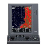
Koden MDC-5500 SERIES Operation Manual (182 pages)
Brand:
Koden
| Category:
Marine Radar
| Size: 3 MB
Table of Contents
Document Revision History
3
Important Notice
4
For Your Safe Operation
5
Break in Procedure of Stored Radar
9
Used Battery and Radar Disposal
10
In Case no Heading and Speed Signals Are Input from Navigation Equipment
11
Table of Contents
12
Contents
14
Introduction
19
Configuration Items
20
System Configuration
20
Option List
22
Chapter 1 Display and Operation
23
Radar Display
23
Upper Left Corner
24
Upper Right Corner
24
Lower Left Corner
24
Lower Right Corner
24
Assitant Info Disp
25
Map Info
26
Operation Unit
28
Menu Usage
30
Turn MENU on and off
30
Select Menu Item
30
Cursor Access Usage
32
Chapter 2 Radar Basic Operation
33
Power ON/OFF
33
Power on
33
Power off
33
Change Brilliance
34
Display Brilliance
34
Panel Brilliance (Operation Unit)
35
Transmission
36
Transmission on
36
Transmission off
36
Tuning Method
37
Change man (Manual) and AUTO
37
Optimized Value Setup Method
37
Change Range Scale
39
Change Range Unit (NM / Km / Sm / Kf / Ky)
39
Adjust Receiver Gain (GAIN)
40
Selection of man GAIN and AUTO GAIN
40
AUTO Adjustment of GAIN
40
MAN Adjustment of GAIN
41
Reject Sea Clutter (Anti-SEA)
42
Selection of man SEA and AUTO SEA
42
AUTO Adjustment of SEA
43
Manual Adjustment of SEA
43
Reject Rain/Snow Clutter (Anti-RAIN)
44
Changing Method of CFAR and man
45
CFAR (Constant False Alarm Rate) Adjustment
45
RAIN man (Manual) Adjustment
46
Change Transmission Pulse Width (SP/LP)
47
Select Display Mode
48
For H up (Head up Mode)
48
For C up (Course up Mode)
49
For N up (North up Mode)
49
For Relative Motion (RM) and True Motion (TM)
50
Reset True Motion
51
Ground and Sea Stabilization
52
SEA (Sea Stabilization)
52
Measurement of Distance by RR and VRM
53
Display Range Rings (RR)
53
Measurement Range (VRM: Variable Range Marker)
54
Measurement of Bearing by EBL
55
Using the EBL/VRM OFFSET
56
Bearing Mode Set up
57
Measurement of Distance/Bearing by PI
58
Measurement Distance/Bearing by ERBL
60
Change ERBL Mark to LINE or RING
62
Change Color and Brightness (Day/Night)
63
Setup Color
63
Setup USER1 and USER2 Color
64
Setup Brightness
65
Color and Brightness Settings Reset
65
Remove the Heading Line / Navigation Data
66
Target Trail
66
Relative Display (R)
68
True Display (T)
68
Off Center
69
Function Key Usage
70
Set Picture Mode
71
Echo Process
72
Correlation Image Echo Process
72
Echo Expansion
73
Interference Rejection (IR)
74
Video Contrast
74
Noise Rejection
75
Echo Color Rejection
75
Pulse Width
76
Inter-Switch
77
Cursor Data
79
CURSOR Setting Menu
79
Setup Own Ship Outline
80
Setup Ship Outline
80
Ferry Mode
81
Display Setup
82
ALL PPI Mode
82
Rotation Margin (H Up, C Up)
82
Rotation Speed
83
Assistant Info Disp
83
Chapter 3 Alarm
85
Collision Avoidance
85
Echo Alarm
85
How to Set Echo Alarm Area. (Fan Type)
85
Map Area Alarm
87
How to Edit Map Area
87
How to Move Map Area
88
How to Add Data to Map Area
89
How to Delete the Data of Map Area
90
How to Clear Entire Block of Map Area Data
90
Guard Zone Alarm
91
How to Set Guard Zone Alarm
91
Nav Line Cross
92
How to Edit
92
How to Move Nav Line
93
How to Add
94
How to Delete
95
How to Clear
95
Alarm On/Off (TT and AIS)
96
Chapter 4 Target (AIS and TT)
97
Common Setting
97
Vector Rel/True
97
CPA/TCPA Alarm
99
Lost Alarm
99
Set AIS ID DISP TYPE
99
Set TT ID DISP TYPE
100
Set ID DISP SIZE
100
Set Input Range
100
Association
101
Automatic Acquisition Area
102
PAST POSN: Past Position
103
Ais
104
Enable AIS Function
104
Select ID
104
Active/Sleep
104
Ship Outline
105
HDG Line
105
Turn Indicator
105
OS Display
105
Os Mmsi
105
AIS Filter
106
Aton ON/OFF
106
AIS Alarm [Sleeping Lost]
107
Types of AIS Target Symbol
108
Tt (Arpa)
111
Limitations of the TT Function
111
Enable TT Function
112
Manual Acquisition
112
Delete TT Target
113
Delete All TT Targets
113
Types of Tracked Target Symbol
114
Chapter 5 Nav Tool
115
Guard Line
115
HL Blink
116
Stern Line
116
Barge Icon
117
Chapter 6 Map Operation
119
MAP Function Display on or off
119
Own Ship Past Track
119
How to Clear OWN SHIP PAST TRACK
120
Target Track Past Position Display
120
Coast Line
121
How to Edit
121
How to Move
123
How to Add
124
How to Delete
125
How to Clear
125
Nav Line
126
Route
127
Event Mkr
128
Area
129
Monitored Route
129
Wpt ID Disp
130
Target Track ID
130
Datum
131
Edit User Datum
131
Position Offset
132
Position Manual Offset
132
Wpt Flag
132
Lat/Lon Line
132
C-MAP Chart Display
133
Chapter 7 System and Maintenance Menu Operation
135
System Menu
135
Change UTC / LOCAL Time
135
User Memory
136
Change USER Memory
136
How to Save to Memory
136
Edit User Name
136
Default User Setting
136
Sound Setting
137
Sound ON/OFF
137
Sound Frequency
137
Key Click ON/OFF
137
External Buzzer Setting
137
LANGUAGE Select
138
Display Infomation (Disp Info)
138
UPPER DISP Setting
139
HELP Window ON/OFF
139
Maintenance Menu
140
BACKUP of Setup Data (Cannot be Used While Transmitting)
140
Internal Save of Setup Data
140
External Save of Setup and Map Data (Cannot be Performed While Transmitting)
141
Parameter Reset
142
MAP/PAST Reset
142
TOTAL HOUR and TX HOUR (Cannot be Used While Transmitting)
143
Menu Setup
143
System Program
144
Version Confirmation
144
How to Update the System Program
145
Chapter 8 Principal of Radar System
147
What Is Radar System
147
Side Lobe
147
Beam Width
148
Characteristics of Radar Radio Wave
148
Target Hardness Reflected
148
Radar Shadow
149
False Image
149
Radar Interference
151
Chapter 9 Simple Fault Diagnosis
153
No Alarm Sound
154
Operation Unit (Panel) Key Is Not Operational
155
TT Is Not Operational
156
No AIS Display
157
Need to Confirm Serial Input
158
No Radar Video Display
159
Chapter 10 Specifications
161
Antenna and Scanner Unit
161
Display and Operation Unit
162
External View and Dimensions
163
Chapter 11 Appendix
167
Menu Tree
167
Chapter 12 Index
179
Advertisement
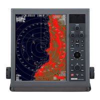
Koden MDC-5500 SERIES Service Manual (186 pages)
Brand:
Koden
| Category:
Marine Radar
| Size: 11 MB
Table of Contents
Important Notice
4
For Your Safe Operation
5
Break in Procedure of Stored Radar
9
Disposal of Used Cells and this Radar
10
Table of Contents
11
Chapter 1 Fault Diagnosis
15
About Alarms
15
Malfunction Detection Step
16
Malfunction Diagnosis Flowchart
17
Initial Malfunction Diagnosis 1
17
Initial Malfunction Diagnosis 2
18
Other Faults (Display Unit)
19
Abnormal Display
20
No Response from the Antenna Scanner Unit
21
Sensitivity Failure
22
No Display of Ship's Bearing, Speed and Latitude/Longitude
23
Operation Unit Abnormality
24
Antenna Scanner Unit Abnormality
25
Synchronization of Screen Abnormality
26
High Voltage Abnormality
26
Pulse Length Control Failure
27
Rotary Abnormality
28
Heading Line and Azimuth Abnormality
29
TT (ATA) Abnormality
30
Chart Display Abnormality
31
No Display of AIS
32
Other Faults (Antenna Scanner Unit)
34
Failure Criterion of Microwave Components
38
Magnetron
38
Front-End Module
38
Limiter
38
Chapter 2 MAINTENANCE MENU
39
Bite
39
Panel Test
39
Diagnose Tt
39
Diagnose Ais
40
Serial Monitor
41
Ant Monitor
42
Sd Card
42
Echo
43
Gain Offset
43
Sea Curve
43
Chapter 3 How to Exchange Components
45
Display Unit
45
Replacement of Fuse
45
Dismantling of Bracket and Rear Case (MRD-108 / MRD-108P)
46
Dismantling of Bracket and Rear Case (MRD-109)
47
Dismantling of Bracket and Rear Case (MRD-111)
48
Exchange of Logic PCB (MRD-108/108P/109/111/MRM-108/108P/110)
49
Exchange of Power Supply PCB (MRD-108/108P/109/111, MRM-108/108P/110)
51
Exchange of LCD Unit (MRD-108/108P)
53
Exchange of LCD Unit (MRD-109)
55
Exchange of LCD Unit (MRD-111)
57
Exchange of Backlight Power PCB (MRD-108/108P)
60
Exchange of Rear Card Connector PCB (MRD-108/108P/MRM-108/108P/110)
61
Exchange of Connector PCB (MRD-109)
62
Exchange of Connector PCB (MRD-111)
63
Operation Unit
64
Exchange of Panel PCB (MRO-108/108P)
64
Exchange of Panel PCB (MRD-111)
67
Exchange of Track Ball (MRO-108/108P)
68
Exchange of Sillcon Key (MRD-111)
70
Antenna Scanner Unit
71
Dismantling of Antenna and Antenna Cover
71
Exchange of Azimuth Pulse Unit and Drive Unit Motor (RB806 / 807 / 717A / 718A / 719A)
73
Exchange of V Ring
75
Exchange of Modulator PCB
80
Exchange of Fan (RB809 Only)
83
Exchange of Fan (RB719A Only)
84
Exchange of Magnetron (RB806)
85
Exchange of Magnetron (RB807,RB808/808P)
87
Exchange of Magnetron (RB809/809P)
89
Exchange of Magnetron (RB717A, RB718A)
91
Exchange of Magnetron (RB719A)
93
Exchange of Transformer (RB809/809P)
95
Exchange of Transformer (RB717A, RB718A)
97
Exchange of Transformer (RB719A)
98
Exchange of MIC (RB806)
100
Exchange of if MODULE (RB807/808/808P/809/809P)
101
Exchange of if PCB, MIC and Limiter Device
102
Chapter 4 Spare Parts and Circuit Diagram
109
Spare Parts
109
Circuit Diagram
142
Interconnection Diagam of 4Kw Scanner Unit (RB806)
143
Interconnection Diagam of 4 Kw Scanner Unit (RB716A)
144
Interconnection Diagam of 6 Kw Scanner Unit (RB807)
145
Interconnection Diagam of 6 Kw/12 Kw Scanner Unit (RB717A/718A)
146
Interconnection Diagam of 12 Kw Scanner Unit (RB808)
147
Interconnection Diagam of 12 Kw Scanner Unit (RB808P)
148
Interconnection Diagam of 25 Kw Scanner Unit (RB809)
149
Interconnection Diagam of 25 Kw Scanner Unit (RB809P)
150
Interconnection Diagram of 25 Kw Scanner Unit (RB719A)
151
Inter Connection Diagram MRD-108/MRD-108P
152
Inter Connection Diagram MRM-108/MRM-108P
153
Inter Connection Diagram MRD-111
154
Inter Connection Diagram MRD-109
155
Inter Connection Diagram MRM-110
156
Circuit Diagram Power Supply PCB
157
Circuit Diagram of BACK LIGHT POWER PCB
159
Circuit Diagram of PANEL BOARD (E63-900*)
160
Circuit Diagram of PANEL BOARD (E68-900*)
161
Circuit Diagram of PANEL BOARD (E73-900*)
162
Circuit Diagram of CONNECTOR PCB (E63-911*)
163
Circuit Diagram of CONNECTOR PCB (E68-910*)
164
Annex
165
Clean up the Trackball
165
Interface
167
Relation between Functions and Input Signal
167
Kind of Input/Output Ports
168
Setup Interface
169
Confirmation of Input Signal
175
Connection of Gyro Convertor S2N
176
Gyro/Log Interface: Connection of ADPC-101 Unit (Non-IMO
178
Connection of LOG Pulse NMEA Converter L1N (200 Pulse/Nautical Mile Only
180
Connection of AIS
181
System Program
183
Version Confirmation
183
How to Update the System Program
184
Advertisement
Related Products
Koden MDC-5512
Koden MDC-5525
Koden MDC-5504
Koden MDC-5506
Koden MDC-5200 SERIES
Koden MDC-5004
Koden MDC-5012
Koden MDC-5025
Koden MDC-5006
Koden MDC-5204
Koden Categories
Marine Radar
Marine Equipment
GPS
Sonar
Monitor
More Koden Manuals
Login
Sign In
OR
Sign in with Facebook
Sign in with Google
Upload manual
Upload from disk
Upload from URL