Sign In
Upload
Manuals
Brands
Kobold Manuals
Measuring Instruments
BGN-H
Kobold BGN-H Manuals
Manuals and User Guides for Kobold BGN-H. We have
1
Kobold BGN-H manual available for free PDF download: Operating Instructions Manual
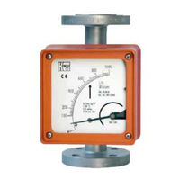
Kobold BGN-H Operating Instructions Manual (30 pages)
Full Metal Variable Area Flow Meter and Counter
Brand:
Kobold
| Category:
Measuring Instruments
| Size: 0 MB
Table of Contents
Table of Contents
2
Identification
4
Supplier/Manufacturer
4
Product Type
4
Product Name
4
Applications
4
Operational Mode and System Design
4
Measuring Principle
4
System Design
4
Input
4
Measured Variable
4
Output6
6
Binary Output
6
KEI 1 or KEI 2 Limit Transducers
6
KEM 1 or KEM 2 Limit Transducers (Special Version)
6
Analog Output with the es Magneto-Electric Transmitter
6
Analog Output with the KINAX 3W2 Angle-Of-Rotation Transmitter
6
Characteristic Values
6
Measuring Accuracy
6
Reference Conditions
6
Measured Error
6
Mounting/Start-Up
7
Device Settings
7
Adjusting the Limit Transducer
7
Operation in Hazardous Areas
8
Ambient Conditions
9
Ambient Temperature Ranges
9
Storage Temperature
9
Climatic Category
9
Degree of Protection
9
Shock Resistance/Vibration Resistance
9
Electromagnetic Compatibility
9
Fluid Conditions
9
Fluid Temperature Ranges
9
Diagrams: Max. Ambient Temperature Based on the Fluid Temperature for the es
9
Fluid Pressure Limit
10
Inlet and Outlet Sections
10
Physical State
10
Density
10
Viscosity
10
Pressure (for Gas Measurement)
10
Pressure Loss
10
Construction Details
11
Type of Construction/Dimensions
11
Aluminum Indicator Housing
11
Dimension Drawing for Heating Connection
11
Indicator Housing Made of Stainless Steel
12
Weight
12
Material
13
Process Connection
13
Magnetic Filter
13
Electrical Connection
14
Wiring Diagram for es Transmitter (Signal Output 4-20 Ma with HART)
14
Wiring Diagram for es Transmitter with 4-20 Ma Output and 2 Limit Transducers
14
Wiring Diagram for es Transmitter with 4- 20 Ma Output, Pulse Output and Limit Transducer
15
Wiring Diagram for Inductive Limit Transducers
15
Wiring Diagram for KINAX 3W2 Transmitter with 4-20 Ma Output, 2 Wires
16
Wiring Diagram for KINAX 3W2 Transmitter with 4-20 Ma Output, 3 Wires
16
Wiring Diagram for KINAX 3W2 Transmitter with 4-20 Ma Output, 4 Wires
17
Wiring Diagram for KEM 1 and KEM 2 Double-Throw Microswitches
17
Indicator Unit
18
Auxiliary Power
18
Ce Mark
18
Order Information
18
Available Accessories
18
Standards and Directives, Certificates and Approvals
18
Safety Instructions
18
Intended Use
18
Installation, Start-Up and Operating Personnel
18
Packaging, Mounting and Shipment
18
Installing and Removing Cone, Float, Damping Sets/Spring Stop
19
Trouble Shooting
19
Returning Devices for Repair and Service
19
Replacement Parts
19
Exploded Views
20
Fitting with Measuring Element
20
Bgn
20
Bgn
21
Indicator Unit
22
Complete Indicator Unit, Local with Scale
22
Complete Indicator Unit with 1 SJ 3,5 N Limit Transducer
22
Complete Indicator Unit with 2 SJ 3,5 N Limit Transducers
22
Complete Indicator Unit with E2 KINAX Ex Transmitter
23
Complete Indicator Unit with E2 KINAX Ex Transmitter and 1 SJ 3,5 N Limit Transducer
23
Indicator Unit with Transmitter Type es Ex HART
23
Decontamination Certificate for Device Cleaning
24
Ec Type Examination Certificate
25
Sales Representatives
30
Notes30
30
Advertisement
Advertisement
Related Products
Kobold BVO Series
Kobold BVO-12 Series
Kobold BVO-11 Series
Kobold BGN
Kobold BGN-S
Kobold BGN-P
Kobold **C3 Series
Kobold **C30M Series
Kobold **C30R Series
Kobold **C34N Series
Kobold Categories
Measuring Instruments
Switch
Transmitter
Accessories
Monitor
More Kobold Manuals
Login
Sign In
OR
Sign in with Facebook
Sign in with Google
Upload manual
Upload from disk
Upload from URL