Sign In
Upload
Manuals
Brands
KOBELCO Manuals
Excavators
Dynamic Acera SK450-VI
KOBELCO Dynamic Acera SK450-VI Excavator Manuals
Manuals and User Guides for KOBELCO Dynamic Acera SK450-VI Excavator. We have
1
KOBELCO Dynamic Acera SK450-VI Excavator manual available for free PDF download: Service Handbook
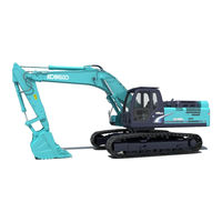
KOBELCO Dynamic Acera SK450-VI Service Handbook (139 pages)
Hydraulic Excavator
Brand:
KOBELCO
| Category:
Excavators
| Size: 6 MB
Table of Contents
Contents
3
General Dimensions
5
Skipping Dimensions
5
Specifications and Performance
7
Engine Specifications
8
Engine Characteristic Curve
9
Hydraulic Components Specifications & Performance
10
Control Curve of Pump
12
At Electric Power Control
12
At Back-Up Mode
12
Hydraulic Cylinder
13
Performance Table
14
Noise Level
15
Measuring Procedure
15
Measuring Position
15
Weight of Components
16
Specified Oil and Grease, and Filter Element LST
17
Lubrication Specifications
17
Fluids & Filters
18
Required Fluids & Quantities
18
Required Filters
18
Lubricant Specifications
19
Summary of Mechatro Control System
22
Mechatro Controller Adjustment
24
Engine Control Input/Output
24
Adjusting the Engine Revolution
24
Mechatronic Control Devices
24
Work Mode Select Switch
25
Buzzer Stop Switch
25
Engine Emergency Stop Knob
25
Measurement of Engine Speed
26
Warming up of Engine
26
Measuring with Diesel Engine Speed Meter
26
Engine Speed Measured Value through Service Diagnosis
26
Measurement of Hydraulic Pressure
27
Preparing to Measure Hydraulic Pressure
27
Place to Install Pressure Gauge
27
Main Circuit
27
Pressure Adjustment Position and Adjusting
28
Main Control Valve
28
Over Load Relief Valve
28
Boost Pressure Main Relief
29
Travel Overload Relief Valve
29
Pilot Relief Valve
29
Swing Motor
30
Swing Main Relief Valve
30
Measuring Travel Performances
31
Travel Speed
31
Deviation of Travel
31
Performances of Parking Brake
32
Drain Rate of Travel Motor
32
Measuring Swing Performances
33
Swing Speed
33
Performance of Swing Brake
33
Performance of Swing Parking Brake
34
Drain Rate of Swing Motor
34
Measuring Attachment Operating Performances
35
Operating Time of Cylinders
35
Oil Tightness of Cylinders
35
Measuring Performances of Swing Bearing
36
Performance Inspection Standard Table
37
Hydraulic Circuit and Components
40
Electric Circuit Diagram
44
Electronically Controlled Fuel System
60
Principle of Operation
60
Electronic Governor
61
Linear DC Motor
61
Control Rack Position Sensor
61
Emergency Engine Stop Lever
61
Electronic Timer
62
Timer Control Valve
63
Advancement of Fuel Injection Timing
63
Electronic Control System
64
System Block Diagram
64
Maintenance of Advanced Fuel Injection Timing
64
Retardation of Fuel Injection Timing
64
Injection Quantity Adjusting Resistor
65
Control of Fuel Injection Quantity
66
Control of Fuel Injection Timing
66
Preheat Control
67
Operating Modes
67
ECU Terminal Configuration
68
Specifications
72
Troubleshooting
73
Inspection Procedures
73
Diagnostic Function
73
Warning Lamp Indications
73
Inspection Flowchart
74
Connection of Multi-Use Tester II
75
Special Tools
75
Reading and Erasing Diagnostic Trouble Codes
77
Past Diagnostic Trouble Codes
78
Erasing Diagnostic Trouble Codes
78
Diagnostic Trouble Codes
79
Diagnostic Trouble Code Issue Conditions and Check Items
79
Service Data
85
Inspection Using ECU Connector
87
ECU Terminal Pin Configuration
87
Inspection Instructions
87
Checks on Transient Troubles
89
Inspection of Electrical Equipment
90
Checking Water Temperature Sensor
90
Checking Engine Speed Sensor
90
Checking Boost Pressure Sensor
91
Output Characteristics
92
Inspection of Timer Control Valve
92
Inspection of Fuel Injection Quantity Adjusting Resistor
92
Dimensions of Attachment
94
Boom Dimensional Drawing
94
Boom Maintenance Standard
95
Clearance of Pin and Bushing
95
Clearance in Thrust Direction
96
Arm Dimensional Drawing
97
Arm Maintenance Standard
98
Bucket Dimensional Drawing
100
STD Bucket
100
Bucket Dimensional Table
100
Dimensional Drawing of Lug Section
101
Dimensional Drawing of Boss Section
102
Pin and Bushing Table of Attachment
103
Name of Pin
103
Types of Pin
104
Dimensions of Pin
105
Name of Bushing
106
Types of Bushing
107
Dimensions of Bushing
108
Maintenance Standard
109
Track Link
109
Upper Roller
110
Lower Roller
111
Front Idler
112
Trackspring
113
Sprocket
114
Working Range
116
Back Hoe
116
Face Shovel
117
Lifting Capacity
118
Tightening Torques for Capscrews and Nuts
124
Screw Size and Tools Nominal Size
125
Capscrew
125
Socket Bolt
125
Set Screw
125
Tightening Torques for Nuts and Sleeves
126
Plug for Hydraulic Equipment
128
PF Screw
128
PT Screw
128
Plug for ORS Joints
129
Plug for Half Clamp
129
Special Spanner for Tube
130
Application of Screw Locking Compound and Sealing Compound
133
For General Use
133
For Specific Location
133
Suction Stopper
134
Components
134
Dimension
134
Applicable Model
134
Upper Frame Lifting Jig
135
Engine Mounting Pedestal
136
Advertisement
Advertisement
Related Products
KOBELCO Dynamic Acera SK450LC-VI
KOBELCO Dynamic Acera SK480-VI
KOBELCO Dynamic Acera SK480LC-VI
Kobelco ACERA Geospec SK460-8
Kobelco ACERA Geospec SK480LC-S
Kobelco SK140SRL-7
Kobelco SK235SRLC-2
Kobelco SK17SR-5
Kobelco ACERA Geospec SK200-8
Kobelco ACERA Geospec SK250-8
KOBELCO Categories
Excavators
Air Compressor
Construction Equipment
Hair Styler
Toy
More KOBELCO Manuals
Login
Sign In
OR
Sign in with Facebook
Sign in with Google
Upload manual
Upload from disk
Upload from URL