Kikusui PCR 500L AC Power Supply Manuals
Manuals and User Guides for Kikusui PCR 500L AC Power Supply. We have 3 Kikusui PCR 500L AC Power Supply manuals available for free PDF download: Operation Manual, Operation Manual Supplement
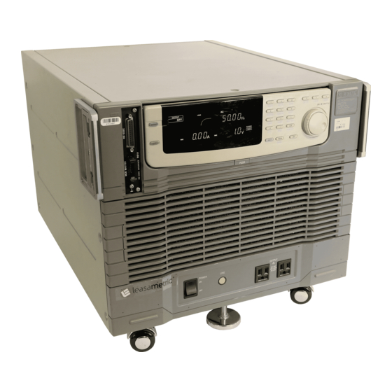
Kikusui PCR 500L Operation Manual (145 pages)
Brand: Kikusui
|
Category: AC Power Distribution
|
Size: 7 MB
Table of Contents
Advertisement
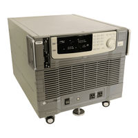
Kikusui PCR 500L Operation Manual (154 pages)
Brand: Kikusui
|
Category: Power Supply
|
Size: 3 MB
Table of Contents

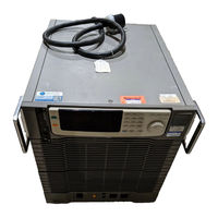
Kikusui PCR 500L Operation Manual Supplement (8 pages)
Brand: Kikusui
|
Category: Power Supply
|
Size: 0 MB
Table of Contents
Advertisement