Sign In
Upload
Manuals
Brands
Kikusui Manuals
Measuring Instruments
KHA3000
Kikusui KHA3000 Manuals
Manuals and User Guides for Kikusui KHA3000. We have
2
Kikusui KHA3000 manuals available for free PDF download: Operation Manual, Firmware Update Manual
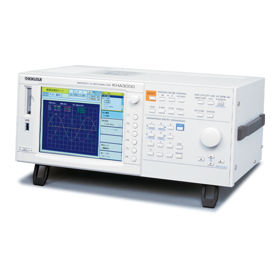
Kikusui KHA3000 Operation Manual (392 pages)
Harmonic/Flicker Analyzer
Brand:
Kikusui
| Category:
Measuring Instruments
| Size: 10 MB
Table of Contents
About this Manual
2
Safety Symbols
2
Notations Used in this Manual
3
Safety Precautions
4
Table of Contents
5
Quick Guide for Wiring Measurement Circuits
21
Wiring Measurement Circuits
22
Single-Phase Two-Wire Circuit
22
Wiring Method
22
Single-Phase Three-Wire Circuit
24
Wiring Method
24
Three-Phase Three-Wire Circuit
26
Wiring Method
26
Three-Phase Four-Wire Circuit
28
Wiring Method
28
Connecting the Voltmeter to External Measurement Points
30
Single-Phase Two-Wire Circuit
31
Single-Phase Three-Wire Circuit
32
Three-Phase Three-Wire Circuit
33
Three-Phase Four-Wire Circuit
34
Overview
35
Overview of the Product
36
Features
36
Conforming Standards of this Product (Harmonic Current)
38
Conforming Standards of this Product (Flicker, Voltage Fluctuation)
38
Test System Configuration
39
Options
40
Multi-Outlet Unit (OT01-KHA)
40
Rack Mount Options (KRB4, KRB200)
40
Installation and Preparation for Use
43
Inspection During Unpacking
44
Notes on Installation Location
45
Using Stands
46
Removing the Handle and Side-Panel Rubber Pads
46
Connecting Power Cord
47
Connecting the Input Power Supply of the Test System
47
Notes on Transfer
48
Wiring Measurement Circuits
49
Common Information on Measurement Circuits
50
Circuit Symbols Used
50
Parts to be Prepared by the Customer
51
Selecting the Type of Electric Wire
51
Prevent an Electric Shock with Terminal Cover
52
Performance of Input Terminals
52
Mechanism of Voltage Measurement
53
Wiring Measurement Circuits
54
Circuit Diagrams
54
Using the Line Impedance Network
56
Connecting a Voltmeter to External Measurement Points
57
Circuit Diagrams
58
Using PT (Potential Transformer)
59
Using CT (Current Transformer)
60
Circuit Diagram
60
Using External Current Shunts
62
Circuit Diagram
62
Connecting External Signals
64
EXT INPUT (BNC Connector)
64
EXT CLAMP (Only for Options)
65
Ext Sync Input
65
Connecting Control Cables
66
Remote Controller Pcr-La
66
Remote Controller Lin-1/Lin-2
66
Measurement Circuit Using Commercial Power Supply
67
Connecting Communication Cables
68
Gpib
68
Rs232C
69
Usb
69
System Setup
71
Turning on the Power
72
Turning on the POWER Switch
72
Turning off the POWER Switch
73
Power-On of the Test System
74
Separate ON/OFF
74
Collective Power-On/Off
76
Switching Displays
77
Types and Names of Basic Views
77
Keys Used to Switch between the Three Basic Views
79
Keys Used to Display the System Setup Display and Other Displays
80
Using the Menu
82
Selecting Menu Items
82
Entering Numeric Values or Characters
83
Displaying a Sub-Menu
83
Key Used to Lock Operation, and Other Keys
84
Locking Key Operation
84
Holding the Display
85
Saving the Current Display
85
Changing the Display Brightness
85
Changing the Buzzer Volume
85
Changing to Local Operation
85
Setting the System
86
Showing the System Setup Display
86
Language, I/F Setting and Buzzer
86
Clock and Printer
88
Updating the Firmware Version and Maintenance
89
Using Assist Function
90
Supporting Security for Users Not Familiar with the Standards
90
Setting the Harmonic Test
91
Test Conditions Setting Displays
92
Using the HA-Observation and Test Conditions Display (Setting During Measurement)
93
Configuration of Test Conditions Setting Menu
94
Limitation Standards, Classes and Nominal Values
95
Measurement Time, Margin Comment Input and Standard Name
96
Power and Class Options
98
Voltage and Current Range, Wiring Method and Scaling
101
Using Scaling Menu Items
106
Delta Transform (Star-Delta Conversion)
107
Adjusting the Phase Difference between Voltage and Current
108
Directly Setting Voltage and Current Ranges
110
Limitation Standards, Equipment and Rated of Equipment
111
Measurement Time, Margin, Comment Input and Standard Name
114
Reference Current/Reference Fundamental Current, Judgment Rsce and Limit Values
115
Voltage and Current Ranges, Wiring Method and Scaling
116
Controlling the AC Power Supply
118
Showing the External Control Display
118
Voltage and Frequency Settings and on Phase
119
Executing Harmonic Tests
121
61000-3-2: Test Flow
122
Setting the LIN and AC Power Supply (61000-3-2)
123
Setting Test Conditions (61000-3-2)
124
Setting Limit Value and Measuring Technique Standards
124
Optimizing the Current Range
125
Input Procedure When Specified Is Selected in the Setting Menu
126
Inputting Comments for Report Printing
127
Starting the Test by Pressing the START Key (61000-3-2)
128
Aborting the Test by Pressing the STOP Key
128
When the Test Is Aborted Automatically
128
When the Test Time Expires (61000-3-2)
129
61000-3-12 2011: Test Flow
130
61000-3-12 2004: Test Flow
132
Setting the LIN and AC Power Supply (61000-3-12)
134
Setting Test Conditions (61000-3-12)
135
Setting Limit Value Standard, Measuring Technique Standard and Equipment
135
Optimizing the Current Range
135
Input Procedure When Specified Is Selected in the Setting Menu
136
Inputting Comments for Report Printing
137
Checking the Third, Fifth and Seventh Harmonics
137
Determining the Limit Value
138
Estimating the Rsce (61000-3-12)
139
Standard Requirements for Impedance
139
Selecting the Limit Value
139
Searching for the Minimum Rsce Value with the Measured Monitor Values Displayed (61000-3-12 2004 Only)
140
Starting the Test by Pressing the START Key (61000-3-12)
142
Aborting the Test by Pressing the STOP Key
142
When the Test Is Aborted Automatically
142
When the Test Time Expires (61000-3-12)
143
When the General Judgment Is PASS
144
When the General Judgment Is FAIL, Increase the Judgment Rsce
144
Overview of the Test Ending Menu
146
Test Ending Menu
148
Save
150
Report Print
150
Exit
152
Analysis
153
AC Power Supply OUTPUT off
154
Observation, Analysis and Judgement of Harmonics
155
Functions of Observation, Analysis and Judgment
156
Selecting the Targets of Observation, Analysis and Judgment
156
Displaying the HA-Observation and Analysis Display (HA-VIEW)
157
View Type List
158
HA-Observation and Analysis Menu
160
Menu Common to All the View Types
160
Browsing Data Frame
161
Dividing the View Area
162
Display Screen When the Scaling Function Is Used
162
View Setting Sub-Menu
163
Waveform
164
2D Harmonics
165
Harmonics
166
Meter
166
Vector
167
List
168
Harmonics List
169
Current Trend
173
Harmonics Trend
174
Result List (with the Standard Judgment Function)
175
Checking the AC Power Supply and Repeatability
178
Checking the AC Power Supply
180
Repeatability Checking
181
Setting the Voltage Fluctuation Test
183
Test Condition Setting Displays
184
Using the Vf-Observation and Test Conditions Display (Setting During Measurement)
185
Configuration of Menu for Setting Voltage Fluctuation Test Conditions
186
Limitation Standards and Nominal Values
187
Measurement Time, Count, and Margin
188
Limit Values for Judgment, Comment Input and Standard Names
190
Voltage Range, Current Range, Wiring Method and Scaling
192
Using Scaling Menu Items
197
Limitation Standards and Nominal Values
198
Measurement Time, Count, and Margin
198
Limit Values for Judgment, Impedance, Input Comment and Standard Names
199
Voltage Range, Current Range, Wiring Method and Scaling
201
Controlling the AC Power Supply
203
Showing the External Control Display
203
Voltage and Frequency Setting and on Phase
204
Executing Voltage Fluctuation Tests
205
61000-3-3 and 61000-3-11: Test Flow
206
Setting the Impedance and AC Power Supply
207
Setting the Impedance
207
Setting Test Conditions (61000-3-3)
208
Setting a Limit Value Standard
208
Optimizing the Current Range
208
Input Procedure with Specified Is Selected in the Setting Menu
209
Inputting Comments for Report Printing
209
Starting the Test by Pressing the START Key (61000-3-3)
210
Aborting the Test by Pressing the STOP Key
211
When the Test Is Aborted Automatically
211
Operation after Starting the Test (61000-3-3, Manual SW)
212
When the Test Time Expires (61000-3-3)
213
When the General Judgment Is PASS
213
When the General Judgment Is FAIL
213
Setting the Impedance Again (61000-3-11)
214
Setting Test Conditions (61000-3-11)
215
Setting the Limit Value Standard
215
Optimizing the Current Range
215
Input Procedure When Specified Value Is Selected in the Setting Menu
216
Inputting Comments for Report Printing
216
Starting the Test by Pressing the START Key (61000-3-11)
217
Aborting the Test by Pressing the STOP Key
217
When the Test Is Aborted Automatically
217
When the Test Time Expires (61000-3-11)
218
When the General Judgment Is PASS
218
When the General Judgment Is FAIL ("100 a Power Supply Declaration")
219
When the General Judgment Is FAIL ("Zmax Declaration")
219
Overview of the Test Ending Menu
220
Test Ending Menu
222
Save
223
Report Print
224
Exit
226
Analysis
227
AC Power Supply OUTPUT off
228
Observation, Analysis and Judgement of Voltage Fluctuations
229
Functions of Observation, Analysis and Judgment
230
Selecting the Targets of Observation, Analysis and Judgment
230
Displaying the Vf-Observation and Analysis Display (Vf-VIEW)
231
View Type List
232
VF-Observation and Analysis Menu
233
Common Menu for All View Types
233
Browsing Segments (Linked)
234
Dividing the View Area
234
Display Screen When the Scaling Function Is Used
234
View Setting Sub-Menu
235
V/I Waveform
236
Rms Waveform
237
List
238
Pinst (St) Waveform
239
CPF Waveform
240
DC Waveform, Dmax Waveform and Tmax (or D(T)>3.3%) Waveform
241
Flicker List
242
Result List (with the Standard Judgment Function)
243
Other Measurements
247
Displaying the Other Measurement Display
248
Entering Sub-Menus
249
Basic Measurement
250
View Select and View Setting
250
Voltage Range, Current Range and Wiring Method
253
Scaling, Cuurent Input Terminal
255
Using Scaling Menu Items
258
LPF and AC Coupling
259
FFT Analyzer
260
Cursor and Vertical Scale (Current)
260
Voltage Range, Current Range and Wiring Method
261
Scaling, Current Input Terminal
261
LPF and AC Coupling
261
In-Rush Current Measurement
262
Select Trigger Channel, Current Trigger and Reset Trigger/Abort
262
Voltage Range, Current Range and Wiring Method
264
Scaling, Current Input Terminal
264
LPF and AC Coupling
264
File Operation
265
Displaying the File Operation
266
Loading and Saving Files
267
Loading a Test Condition File
268
Saving a Test Condition File
269
Folder and File Configurations
270
Specific Folders and Date-Specific Folders
270
File
271
Storage Media
272
Compactflash Card
272
USB Flash Drive
273
Setting the Storage Media
274
Remote Control
275
Overview of Remote Control
276
VISA Library
276
Using the RS232C Interface
278
Using the GPIB Interface
280
Using the USB Interface
281
Overview of Messages
282
SCPI Command Syntax
282
Parameters
285
Command Description in this Manual
287
IEEE 488.2 Common Commands
288
Measurements in General
291
Setting the Operation Mode
292
Setting Linked/Independent of the Input Circuits
292
Setting the Current Input Terminals
292
Setting the PLL Source to Synchronize with the AC Power Supply
293
Setting the Wiring Method of a Measurement Circuit
294
Setting the Type of Input Coupling
294
Setting the Anti-Aliasing Filter
294
Current Range, Voltage Range and Auto Range
295
Scaling
297
Harmonic Measurement Mode (General)
299
Setting the Limit Value Standard
299
Setting the Measuring Technique Standard
300
Setting the Standard Name
300
Setting the Nominal Values
301
Setting the Margin
302
Setting the Measurement Time
302
Comment Input
302
Operation Type of the EUT
303
Setting the Reference Impedance
303
Harmonic Measurement Mode (61000-3-2)
304
Setting the Class of the EUT
304
Class a Condition (JIS C61000-3-2)
304
Class C Conditions
304
Class D Conditions
306
Harmonic Measurement Mode (61000-3-12)
307
Setting the Class of the EUT
307
Setting the Reference Fundamental Current
307
Setting the Judgment Rsce
308
Setting the Limit Value to be Applied
308
Setting the Nominal System Voltage
308
Setting the Rated Value
309
Voltage Fluctuation Measurement Mode (General)
310
Setting the Limit Value Standard
310
Setting the Measuring Technique Standard
310
Setting the Standard Name
311
Setting the Nominal Values
312
Comment Input
312
Voltage Fluctuation Measurement Mode (61000-3-3)
313
Measurement Time, Measurement Count and Limit Values
313
Setting the Margins
315
Voltage Fluctuation Measurement Mode (61000-3-11)
316
Measurement Time, Measurement Count and Limit Values
316
Setting the Margins
317
Impedance
318
Test Execution (Trigger Function)
319
Sequence 1 (Acquire)
319
Sequence 2 (RUSH)
320
Sequence 3 (TEST)
322
Aborting Measurement
323
Judgment
323
Querying Measurement Data
324
Querying Current
326
Querying Harmonic Current
327
Querying a Momentary Flicker Value
328
Querying a Frequency
329
Querying a Voltage Phase Angle
329
Querying Power
330
Querying Voltage
331
Controlling the AC Power Supply
332
Setting the AC Power Supply
332
System Setting
334
Buzzer
334
Setting the Date and Time
334
Status Registers and Status Report Function
337
IEEE 488.2 Register Model
339
Status Byte Register
339
Event Status Register (Standard Event Status Resister)
340
SCPI Register Model
341
Operation Status Register (Status:operation)
341
Questionable Status Register (Status:questionable)
343
Preset Status
345
Default Conditions
346
Maintenance
349
Cleaning and Checking
350
Replacing the Backup Battery
350
Replacing a Fuse
350
Calibration
351
Specifications
353
Common Specifications of Input Section
354
Measurement and Display Items
355
Voltage Measurement Function
355
Current Measurement Function
356
External Current Input Terminal (EXT INPUT)
356
Power Measurement Function
357
Frequency Measurement Function
357
Phase Measurement Function
357
Harmonic Current Measurement Function
358
Harmonic Voltage Measurement Function (Measurement Power Supply Quality Check Function)
359
Flicker/Voltage Fluctuation Analysis Function
359
General-Purpose Measurement Function (OTHER Mode)
360
Scaling Function
360
Communication Interface
360
Removal Data Storage
360
External Equipment Control Function
361
General Specifications
361
Outside Dimensions
362
Appendix
363
A Basic Terms and Definitions B Messages
366
C Error List
373
D Factory Default Settings List
376
Initializing this Product
376
E Report Printing Format
380
Terms Used for the Report Printing Format
383
F Troubleshooting
385
Index
387
Advertisement
Kikusui KHA3000 Firmware Update Manual (2 pages)
Brand:
Kikusui
| Category:
Measuring Instruments
| Size: 0 MB
Table of Contents
Package Contents
1
Be Sure to Read the Following
1
Items that Are Necessary to Update the Firmware
1
Update Procedure
1
Confirming that the Compactflash Card Is Operating Normally
1
Copy the Firmware File to the Compactflash Card
1
Update the Firmware
2
Reset the Settings after the Update Process Is Completed
2
Trademarks
2
Advertisement
Related Products
Kikusui KHA1000
Kikusui KJM6710
Kikusui KJM6310
Kikusui KJM6335
Kikusui KMP1000
Kikusui KFM2151
Kikusui KDS6-0.2TR
Kikusui 149-10A
Kikusui 164E
Kikusui 418B
Kikusui Categories
Power Supply
Test Equipment
Measuring Instruments
Racks & Stands
Controller
More Kikusui Manuals
Login
Sign In
OR
Sign in with Facebook
Sign in with Google
Upload manual
Upload from disk
Upload from URL