Sign In
Upload
Manuals
Brands
Kidde Manuals
Control Unit
ARIES
Kidde ARIES Manuals
Manuals and User Guides for Kidde ARIES. We have
1
Kidde ARIES manual available for free PDF download: Installation, Operation And Maintenance Manual
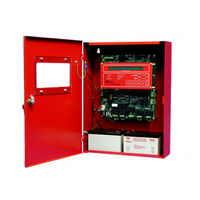
Kidde ARIES Installation, Operation And Maintenance Manual (282 pages)
Fire Alarm/Suppression
Brand:
Kidde
| Category:
Control Unit
| Size: 2 MB
Table of Contents
Foreword
3
Terms and Abbreviations
4
Safety Summary
5
Table of Contents
9
Table of Contents
10
List of Figures
15
List of Appendices
21
Chapter 1 System Overview
23
System Description
23
1-1.1 Standard Features
24
Control Unit Components
25
1-2.1 Display
25
LCD and Leds
25
Digit and Functionality Keys
26
Operator Control Keys
26
Printed-Circuit Board (PCB)
26
ARIES Cabinet
28
Power-Supply/Battery-Charger Assembly
28
Batteries
29
Optional Devices
29
Remote Display/Control Module (RDCM)
29
ATM Series Driver Modules
30
Model ATM-L Annunciator Driver Module
30
Model ATM-R Relay Driver Module
30
Network Interface Card (NIC)
30
Intelligent Interface Module (IIM)
31
Fiber Optic Converter Card
31
Trim Ring
32
Smartone Detectors
32
Smartone Ionization Smoke Detector, Model CPD-7052
33
Smartone Photoelectric Smoke Detector, Model PSD-7152
33
Smartone Thermal Detector, Model THD-7252
33
Detector Bases
34
Flanged Detector Base, Model 6SB
34
Flangeless Detector Base, Model 4SB
34
1-4.5 Detector Base Adapter, Model MA-002
34
1-4.6 Duct Housing, Model DH-2000
35
Smartone Addressable Modules
35
1-5.1 Addressable Monitor Module, Model AI
35
1-5.2 ORION-XT Interface Module, Model PALM
36
1-5.3 Addressable Alarmline Module, Model AAM
36
Addressable Relay Module, Model AO
37
Addressable Signal Module, Model ASM
37
Remote Releasing Module
37
Isolator Modules
39
Specifications
40
1-7.1 Electrical Specifications
40
1-7.1.1 Primary AC Power
40
1-7.1.2 Battery and Charging Circuit
40
1-7.1.3 Signaling Line Circuit
40
1-7.2 Mechanical Specifications
40
1-7.3 Environmental Specifications
40
1-7.4 Notification-Appliance and Releasing Circuits
41
1-7.5 Relays
41
1-7.6 Auxiliary Outputs
41
1-7.7 Electrical Supervision
42
Chapter 2 Installation
43
Preparing for Installation
43
2-1.1 Control-Unit Components
43
2-1.2 Materials/Tools Required
43
2-1.3 Determining Installation Location
44
Codes and Standards
44
Installation Overview
45
2-3.2 Step Two: Installing the ARIES Power Supply and Main PCB
45
2-3.3 Step Three: Connecting AC Power and Standby Battery
45
2-3.4 Step Four: Auto-Configuring the System
45
2-3.5 Step Five: Uploading the Application Program and Performing the Pre-Test
46
2-3.6 Step Six: Performing Final System Test and Commissioning the System
46
2-3.7 Step Seven: Installing the Actuation Devices and Extinguishing System
46
2-3.8 Step Eight: Performing Final Installation Procedures
46
Mounting the Cabinet/Enclosure
47
Preparing the Enclosure for Wall Mounting
48
Surface Mounting
48
2-4.3 Semi-Flush Mounting
49
Installing the Power Supply
49
Installing the Printed Circuit Board (PCB)
51
AC and DC Power Connections
53
AC Power Connection
53
2-7.2 DC Power Connection
54
Signaling Line Circuit
55
SLC Wiring Requirements
55
Class-B, Style-4 Wiring Requirements
55
2-8.1.2 Class-A, Style-6 Wiring Requirements
58
2-8.1.3 Special Class-A, Style-7 Requirements
60
Notification Appliance Circuits
61
Combination Circuits
62
2-10.1 Combination Circuits Used as Nacs
62
Combination Circuits Used as Releasing Circuits
63
Releasing Circuits
64
2-11.1 Releasing Circuits for Actuator Assembly
64
2-11.2 Releasing Circuits for Single Control Head or Solenoid Valve
65
Releasing Circuits for Dual Control Heads or Solenoid Valves
66
Auxiliary Power Outputs
66
Rs-485 Communications Circuit
67
Relays
70
Rs-232 Communications Port
71
USB Communications Port
72
Network Interface Card
72
How to Install a NIC
73
Network Wiring
73
Fiber-Optic Converter Card
76
Intelligent Interface Module
81
Chapter 3 System Operations
83
ARIES System Operations Overview
83
System Operation
83
3-2.1 Operating States
83
3-2.2 Outputs Activation
84
3-2.3 Operator Keys
84
3-2.4 Status Indicating Leds
86
3-2.5 Operating Instructions
87
Menu Operation
87
Normal Operation
87
3-2.5.2.1 Menu Functions
88
Isolate Menu Functions
95
3-2.5.2.3 List Menu Functions
102
3-2.5.2.4 Set Menu Functions
113
Positive Alarm Sequence
139
3-2.5.5.2 What to Do When PAS Occurs
186
3-2.5.5.3 Alarm Verification
187
Supervisory State
188
What to Do When Alarm Verification Occurs
188
How to Reset the Control Unit after a Supervisory Condition
189
What to Do When a Supervisory Event Occurs
189
Pre-Alarm State
190
How to Reset the Control Unit after a Pre-Alarm Condition
191
Pre-Alarm Silencing
191
What to Do When a Pre-Alarm Occurs
191
3-2.5.8.1 Alarm Events
192
Concurrent States
192
3-2.5.8.2 Hierarchy for Display of Concurrent Events
194
3-2.5.8.3 How Concurrent Events Are Displayed
194
3-2.5.8.4 What to Do When a Level-1 Message Is Displayed
196
3-2.5.8.5 Level-2 Event Display
196
What to Do When Level-2 Messages Are Displayed
197
Level-3 and Lower-Level Event Display
198
What to Do When Level-3 and Lower-Level Messages Are Displayed
198
Level-3 Display Limitations
199
3-2.6 System Start-Up
200
Preliminary Procedures
200
Initial Power-Up and Control-Unit Checkout
200
Initial Signaling-Line-Circuit Configuration
202
Site-Specific Programming
204
System Configuration Via the Auto-Setup Routine
204
System Configuration Via the ACT Configuration Program
204
Network System Operation
204
3-3.1 Communications
207
Network Event Broadcasts
207
3-3.3 Operator Control
207
3-3.4 Event Recording
207
Accessing Remote Node Menus Via Keypad
208
Configuration Uploads/Downloads
208
Event Output Control (EOC)
208
Menu Routines
208
3-3.8.1 Control Units with a Non-Zero Group Number
209
Network Group 0
209
Network Groups
209
3-3.9.1 Operator-Driven Menu State
211
3-3.9.2 Event-Driven States
211
Network Outputs Activation
211
Operating States
211
Operator Control Keys
211
Network Display Messages
212
Remote Trouble Events
212
Status-Indicating Leds
212
Remote Alarm Events
213
Remote Positive-Alarm-Sequence (PAS) Events
213
Remote Alarm-Verification Events
214
Remote Supervisory Events
215
How Concurrent Remote Events will be Displayed
216
Remote Level-1 Event Display
216
Remote Pre-Alarm Events
216
Remote Level-2 Event Display
218
3-3.20.3 Remote Level-3 and Lower-Level Event Display
219
Network Start-Up
219
3-3.21.1.1 Network-Interface-Card (NIC) Installation and Wiring
220
3-3.21.1.2 Initial Configuration
220
3-3.21.1.3 Activating the Network
220
Special Procedures for Networked Systems
220
3-3.21.1.4 Network Maintenance
222
3-3.21.1.5 Removing Power from a Control Unit
223
3-3.21.1.6 Resynchronizing the Network
224
Chapter 4 Inspection, Testing and Maintenance
227
Scheduled System Maintenance
227
Semi-Annual and Annual Testing
227
Lamp Test
227
Battery Test
227
4-2.3 Initiating-Devices Test
228
4-2.4 Walk Test
228
Sequence of Operation
228
Chapter 5 Troubleshooting
231
Introduction
231
Chapter 6 Parts List
255
Introduction
255
Appendix Abattery Calculations
259
Appendix B
266
Wiring Requirements for ARIES Signaling Line Circuit
266
Appendix C
267
Listed and Approved Releasing Devices
267
Appendix D
275
Appendix E
275
Routings for Power-Limited and Non-Power-Limited Wiring
275
APPENDIX F Central-Station Operation
277
Appendix G
280
Factory Mutual Requirements for Pre-Action and Deluge Sprinkler Systems
280
Advertisement
Advertisement
Related Products
Kidde AEGIS 84-732001-001
Kidde AEGIS 84-732001-201
Kidde Atwood KN-COB-B
Kidde Atwood KN-COPP-B
Kidde Alarmline II
Kidde Alarmline II Analogue
Kidde AlarmLine II ADLCU
Kidde Alarmline II Digital EN
Kidde Excellence Series
Kidde GSA-REL
Kidde Categories
Smoke Alarm
Carbon Monoxide Alarm
Security System
Fire Alarms
Security Sensors
More Kidde Manuals
Login
Sign In
OR
Sign in with Facebook
Sign in with Google
Upload manual
Upload from disk
Upload from URL