Sign In
Upload
Manuals
Brands
Keysight Technologies Manuals
Power Supply
N7973A
Keysight Technologies N7973A Manuals
Manuals and User Guides for Keysight Technologies N7973A. We have
1
Keysight Technologies N7973A manual available for free PDF download: Operating And Service Manual
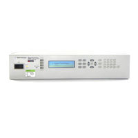
Keysight Technologies N7973A Operating And Service Manual (358 pages)
Advanced Power System
Brand:
Keysight Technologies
| Category:
Power Supply
| Size: 7.12 MB
Table of Contents
Table of Contents
3
Legal and Safety Information
11
Legal Notices
11
Software
11
License Files
11
Warranty
12
Certification
12
US Government Rights
12
Waste Electrical and Electronic Equipment (WEEE) Directive 2002/96/EC
12
Safety Notices
13
Safety Symbols
14
1 Quick Reference
15
Introduction to the Instrument
16
Advanced Power System at a Glance
16
Front Panel at a Glance
17
Front Panel Display at a Glance
18
Front Panel Keys at a Glance
19
Rear Panel at a Glance
20
Power Dissipator at a Glance
21
Front Panel Menu Reference
22
Command Quick Reference
26
ABORT Subsystem
26
Calibrate Subsystem
26
Display Subsystem
26
Fetch Subsystem
27
Format Subsystem
27
Hcopy Subsystem
28
IEEE-488 Common Commands
28
Initiate Subsystem
28
LXI Command
28
Measure Subsystem
29
Output Subsystem
29
Sense Subsystem
30
[Source:]Arb Subsystem
31
[Source:]Current Subsystem
32
[Source:]Digital Subsystem
32
[Source:]Function Command
33
[Source:]List Subsystem
33
[Source:]Power Query
33
[Source:]Resistance Subsystem
34
[Source:]Step Command
34
[Source:]Voltage Subsystem
34
Status Subsystem
35
System Subsystem
35
Trigger Subsystem
36
Model Features and Options
37
Model Features
37
Accessories/Options
39
Specifications and Characteristics
40
Introduction
40
Specifications - Keysight N6900 Series
41
Specifications - Keysight N7900 Series
42
Specifications - Keysight N6900/N7900 High Voltage Series
44
Supplemental Characteristics - Keysight N6900 Series
45
Supplemental Characteristics - Keysight N7900 Series
49
Supplemental Characteristics - Keysight N6900/N7900 High Voltage Series
52
Common Characteristics
54
Output Impedance Graphs
56
Inductive Load Boundary
58
Output Quadrants
59
Voltage Programming Response
60
Output Dynamic Response
60
Measurement Accuracy and Resolution - with Shorter Measurement Intervals
61
Dimension Diagrams - All Dimensions in Millimeters
62
2 Installing the Instrument
65
Before Installation or Use
66
Inspect the Unit
66
Check for Items Supplied
66
Review Safety Information
67
Observe Environmental Conditions
67
Provide Adequate Air Flow
67
Single Unit Connections
68
Line Cord Connection
68
Sense Connections
69
Output Connections
69
Single Load Connections
71
Multiple Load Connections
72
Remote Sense Connections
72
Additional Load Considerations
75
Parallel Connections
76
Parallel Description
76
Sharing Cable Fabrication
77
Load, Sense, and Sharing Connections
77
Series Connections
79
Series Description
79
Load, Sense, and Diode Connections
80
Series Diode Considerations
81
Capacitance Limits
82
Additional Cautions When Using a Boost Supply in Series
82
Power Dissipator Connections
83
The N7909A Power Dissipator
83
Power Cable Fabrication
83
Power Dissipator Connections - 1 Kw Units
84
Power Dissipator Connections - 2 Kw Units
85
Interface Connections
86
GPIB Connections
86
USB Connections
86
LAN Connections - Site and Private
87
Digital Port Connections
88
Rack Mounting
89
Installing the Instrument
89
Black Box Recorder
91
Installing the BBR
91
3 Getting Started
92
Using the Front Panel
93
Turn the Unit on
93
Set the Output Voltage
93
Set the Output Current
94
Set Over-Voltage Protection
95
Enable the Output
96
Use Built-In Help System
97
Remote Interface Configuration
98
Introduction
98
USB Configuration
98
GPIB Configuration
98
LAN Configuration
99
Modifying the LAN Settings
100
Using the Web Interface
103
Using Telnet
104
Using Sockets
104
Interface Lockout
104
4 Using the Advanced Power System
105
Programming the Output
106
Set the Output Priority Mode
106
Set the Output Voltage
106
Set the Output Current
107
Set the Slew Rate
107
Set the Output Bandwidth
108
Set the Output Resistance
109
Enable the Output
109
Configure the Output Relays
110
Programming Output Protection
112
Introduction
112
Set the Over-Voltage Protection
113
Set the Over-Current Protection
113
Output Watchdog Timer
114
User-Defined Protection
115
Clear Output Protection Functions
115
Protection Shutdown Behavior
115
Programming Output Transients
117
Output Transients
117
Common Actions for All Transients
117
Programming a Step Transient
120
Programming a List Transient
121
Programming an Arbitrary Waveform
125
Sequencing the Output
127
Turn-On Turn-Off Behavior
127
Turn-On/Turn-Off Delays
128
Enabling/Disabling the Output
128
Sequencing Multiple Units
129
Making Measurements
132
Average Measurements
132
Number of Power Line Cycles (NPLC)
132
Measurement Windowing
133
Seamless Current Measurement Ranging
133
Amp-Hour and Watt-Hour Measurements
134
Temperature Measurements
134
Digitized Measurements
135
Measurement Triggering
137
Using Expression Signal Routing
142
Signal Routing Overview
142
Defining Signal Expressions
143
Configuring Threshold Comparators
145
Specifying Signal Expression Targets
146
Expression Constraints
147
Expression Examples
148
Programming the Digital Port
151
Digital Control Port
151
Bi-Directional Digital I/O
152
Digital Input
153
Expression<1-8
153
External Trigger I/O
154
Fault Output
154
Inhibit Input
155
Fault/Inhibit System Protection
155
Output Couple Control
156
External Data Logging (Elog)
158
External Data Logging
158
Select the Measurement Function and Range
158
Specify the Integration Period
159
Select the Elog Trigger Source
160
Initiate and Trigger the Elog
160
Periodically Retrieve the Data
161
Terminate the Elog
161
Black Box Data Recording
162
Black Box Recorder
162
Logged Data
163
BBR Status
163
BBR Period
163
BBR Length
163
Snapshot Operation
164
Snapshot Event Tags
164
BBR Clock Setup
165
BBR Alignment
165
Introduction
167
Current Sharing Operation
167
Enable the Current Sharing Function
168
Program the on Couple and off Couple Function
168
Program the Output Voltage and Current
169
Program a Step Function for Additional Output Changes
170
Enable the Output and Trigger Additional Output Changes
171
Specification Effects
172
Current Sharing Effects
173
Current Sinking Operation
174
Current Sinking
174
Power Dissipator Operation
175
Querying the Power Dissipator
175
System-Related Operations
177
Instrument Identification
177
Instrument State Storage
177
Front Panel Display
178
Front Panel Lock-Out
178
Password Protection
179
Voltage Priority
180
Priority Mode Tutorial
180
Current Priority
181
Current Sharing Tutorial
182
Current Sharing Calculations
182
Sharing Deviation for Units of Equal Power (Either 1 Kw or 2 Kw)
183
Sharing Deviation for Units of Mixed Power (1 Kw Paralleled with 2 Kw)
183
5 Using the Power Assistant Software
185
Introduction
186
Using the Meter View
187
Configuring Signal Routing
189
Routing Signals
189
Downloading the Routing
190
Saving the Routing File
191
Viewing the SCPI Commands
191
Source Icon Descriptions
192
Operator Icon Descriptions
193
Target Icon Descriptions
194
Signal Routing Examples
194
Black Box Data Recording
198
Making a Snapshot
198
Retrieving the Snapshot
198
Viewing the Snapshot
199
Configuring the Display
199
Viewing Snapshot Events
200
Exporting the Snapshot Data
201
Saving the Snapshot File
201
6 SCPI Programming Reference
202
IO Libraries and Instrument Drivers
202
Web Interface
202
Example Programs
202
Introduction to the SCPI Language
203
Introduction
203
Keywords
204
Command Separators and Terminators
204
Syntax Conventions
205
Parameter Types
206
Device Clear
207
Typical Command Processing Times
207
Commands by Subsystem
209
Abort Subsystem
210
ARB Subsystem
211
Calibrate Subsystem
214
Current Subsystem
218
Digital Subsystem
222
Display Subsystem
225
Fetch Subsystem
226
Format Subsystem
230
Function Command
231
Hcopy Subsystem
232
IEEE-488 Common Commands
233
Initiate Subsystem
239
LIST Subsystem
240
LXI Command
243
Measure Subsystem
244
Output Subsystem
247
Power Query
254
Resistance Subsystem
255
Sense Subsystem
256
[Source] Subsystem
263
Status Subsystem
264
STEP Command
269
System Subsystem
270
Trigger Subsystem
276
Voltage Subsystem
280
Status Tutorial
285
Status Registers
285
Operation Status Group
285
Questionable Status Group
286
Standard Event Status Group
287
Status Byte Register
288
Error and Output Queues
288
Status Diagram
289
Trigger Tutorial
290
Trigger Sources
290
Trigger Destinations
290
Trigger Diagram
291
Reset State (*RST)
292
SCPI Error Messages
296
Compatibility Commands
304
Channel Parameter
304
Aliased Commands
304
Code Compatible Commands
304
Commands and Parameters that Work Differently
306
7 Verification and Calibration
307
Recommended Test Equipment and Setups
308
Test Equipment
308
Measurement Techniques
309
Test Considerations
309
Verification Setups
310
Calibration Setups
310
Performance Verification
311
Introduction
311
Voltage Programming and Readback Accuracy
311
Constant Voltage Load Effect
312
Constant Voltage Ripple and Noise
312
Transient Recovery Time
313
Current Programming and Readback Accuracy
314
Constant Current Load Effect
314
Current Sink Capability Verification
315
Calibration Procedure
316
Introduction
316
Calibration Interval
317
Enter Calibration Mode
317
Voltage Calibration
317
Voltage Common Mode Rejection Ratio Calibration
318
Current Temperature Coefficient Calibration
318
Current Calibration
319
Current Sharing Calibration
320
Resistance Bottom-Out Calibration
321
Enter a Calibration Date
321
Save Calibration and Log out
321
Test Record Forms
322
N6950A/N6970A
322
N6951A/N6971A
323
N6952A/N6972A
324
N6953A/N6973A
325
N6954A/N6974A
326
N6950A/N6970A with Option 301
327
N6951A/N6971A with Option 301
328
N6952A/N6972A with Option 301
329
N6953A/N6973A with Option 301
330
N6954A/N6974A with Option 301
331
N7950A/N7970A
332
N7951A/N7971A
333
N7952A/N7972A
334
N7953A/N7973A
335
N7954A/N7974A
336
N6976A
337
N6977A
338
N7976A and N6976A with Option 301
339
N7977A and N6977A with Option 301
340
8 Service and Maintenance
341
Introduction
342
Types of Service Available
342
Before Returning the Unit
342
Repackaging for Shipment
342
Cleaning
343
Self-Test Procedure
344
Power-On Self-Test
344
User-Initiated Self-Test
344
Firmware Update
345
Firmware Versions
345
Software Required
345
Update Procedure
346
Restricting Access
346
Option Installation
347
Obtaining the License
347
Instrument Sanitize
348
Sanitizing the Black Box Recorder
348
Calibration Switches
349
Accessing the Calibration Switch
349
Switch Functions
349
Battery Replacement
350
Installing the Instrument
350
Redundant Ground for 400 Hz Operation
352
Hardware and Tools Required (Customer -Supplied)
352
Installation Procedure
352
Disassembly
353
Electrostatic Discharge (ESD) Precautions
353
Tools Required
353
General Disassembly Procedure
353
Index
355
Advertisement
Advertisement
Related Products
Keysight Technologies N7970A
Keysight Technologies N7971A
Keysight Technologies N7972A
Keysight Technologies N7974A
Keysight Technologies N7976A with Option 301
Keysight Technologies N7977A with Option 301
Keysight Technologies N7952A
Keysight Technologies N7953A
Keysight Technologies N7954A
Keysight Technologies N7951A
Keysight Technologies Categories
Measuring Instruments
Test Equipment
Control Unit
Portable Generator
Power Supply
More Keysight Technologies Manuals
Login
Sign In
OR
Sign in with Facebook
Sign in with Google
Upload manual
Upload from disk
Upload from URL