Sign In
Upload
Manuals
Brands
Keysight Technologies Manuals
Test Equipment
InfiniiVision MSO-X 3034A
Keysight Technologies InfiniiVision MSO-X 3034A Manuals
Manuals and User Guides for Keysight Technologies InfiniiVision MSO-X 3034A. We have
1
Keysight Technologies InfiniiVision MSO-X 3034A manual available for free PDF download: User Manual
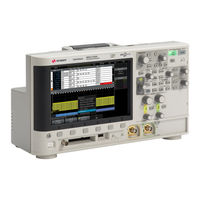
Keysight Technologies InfiniiVision MSO-X 3034A User Manual (432 pages)
Brand:
Keysight Technologies
| Category:
Test Equipment
| Size: 7.61 MB
Table of Contents
Infiniivision 3000 X-Series Oscilloscopes-At a Glance
4
In this Guide
6
Table of Contents
9
1 Getting Started
25
Inspect the Package Contents
25
Install the Optional LAN/VGA or GPIB Module
28
Tilt the Oscilloscope for Easy Viewing
28
Power-On the Oscilloscope
29
Connect Probes to the Oscilloscope
30
Maximum Input Voltage at Analog Inputs
31
Do Not Float the Oscilloscope Chassis
31
Input a Waveform
31
Recall the Default Oscilloscope Setup
32
Use Auto Scale
32
Compensate Passive Probes
34
Learn the Front Panel Controls and Connectors
35
Front Panel Overlays for Different Languages
41
Learn the Rear Panel Connectors
43
Learn the Oscilloscope Display
45
Access the Built-In Quick Help
46
2 Horizontal Controls
50
To Adjust the Horizontal (Time/DIV) Scale
50
To Adjust the Horizontal Delay (Position)
51
Panning and Zooming Single or Stopped Acquisitions
52
To Change the Horizontal Time Mode (Normal, XY, or Roll)
52
XY Time Mode
53
To Display the Zoomed Time Base
56
To Change the Horizontal Scale Knob's Coarse/Fine Adjustment Setting
57
To Position the Time Reference (Left, Center, Right)
58
Searching for Events
58
To Set up Searches
59
To Copy Search Setups
59
Navigating the Time Base
60
To Navigate Time
60
To Navigate Search Events
60
To Navigate Segments
61
3 Vertical Controls
64
To Turn Waveforms on or off (Channel or Math)
64
To Adjust the Vertical Scale
65
To Adjust the Vertical Position
65
To Specify Channel Coupling
65
To Specify Channel Input Impedance
66
To Specify Bandwidth Limiting
67
To Change the Vertical Scale Knob's Coarse/Fine Adjustment Setting
67
To Invert a Waveform
68
Setting Analog Channel Probe Options
68
To Specify the Channel Units
69
To Specify the Probe Attenuation
69
To Specify the Probe Skew
70
To Calibrate a Probe
70
4 Math Waveforms
73
To Display Math Waveforms
73
To Perform Transforms or Filters on an Arithmetic Operation
75
To Adjust the Math Waveform Scale and Offset
75
Units for Math Waveforms
75
Math Operators
76
Add or Subtract
76
Multiply or Divide
77
Math Transforms
78
Differentiate
79
Integrate
80
FFT Measurement
83
Square Root
90
Ax + B
90
Square
91
Absolute Value
92
Common Logarithm
92
Natural Logarithm
93
Exponential
93
Base 10 Exponential
93
Math Filters
94
High Pass and Low Pass Filter
94
Math Visualizations
95
Magnify
96
Measurement Trend
96
Chart Logic Bus Timing
98
Chart Logic Bus State
99
5 Reference Waveforms
101
To Save a Waveform to a Reference Waveform Location
101
To Display a Reference Waveform
102
To Scale and Position Reference Waveforms
103
To Adjust Reference Waveform Skew
103
To Display Reference Waveform Information
104
To Save/Recall Reference Waveform Files To/From a USB Storage Device
104
6 Digital Channels
105
To Connect the Digital Probes to the Device under Test
105
Probe Cable for Digital Channels
106
Acquiring Waveforms Using the Digital Channels
109
To Display Digital Channels Using Autoscale
109
Interpreting the Digital Waveform Display
110
To Change the Displayed Size of the Digital Channels
111
To Switch a Single Channel on or off
112
To Switch All Digital Channels on or off
112
To Switch Groups of Channels on or off
112
To Change the Logic Threshold for Digital Channels
112
To Reposition a Digital Channel
113
To Display Digital Channels as a Bus
114
Digital Channel Signal Fidelity: Probe Impedance and Grounding
117
Input Impedance
117
Probe Grounding
119
Best Probing Practices
121
7 Serial Decode
123
Serial Decode Options
123
Lister
124
Searching Lister Data
126
To Adjust Waveform Intensity
129
8 Display Settings
130
To Set or Clear Persistence
131
To Clear the Display
132
To Select the Grid Type
132
To Adjust the Grid Intensity
133
To Freeze the Display
133
9 Labels
135
To Turn the Label Display on or off
135
To Assign a Predefined Label to a Channel
136
To Define a New Label
137
To Load a List of Labels from a Text File You Create
138
To Reset the Label Library to the Factory Default
139
10 Triggers
141
Adjusting the Trigger Level
142
Forcing a Trigger
143
Edge Trigger
144
Edge then Edge Trigger
146
Pulse Width Trigger
147
Pattern Trigger
150
Hex Bus Pattern Trigger
152
OR Trigger
153
Rise/Fall Time Trigger
154
Nth Edge Burst Trigger
155
Runt Trigger
157
Setup and Hold Trigger
159
Video Trigger
160
To Set up Generic Video Triggers
164
To Trigger on a Specific Line of Video
165
To Trigger on All Sync Pulses
166
To Trigger on a Specific Field of the Video Signal
167
To Trigger on All Fields of the Video Signal
168
To Trigger on Odd or Even Fields
169
USB Trigger
172
Serial Trigger
174
11 Trigger Mode/Coupling
175
To Select the Auto or Normal Trigger Mode
176
To Select the Trigger Coupling
177
To Enable or Disable Trigger HF Reject
179
To Enable or Disable Trigger Noise Rejection
179
External Trigger Input
180
Maximum Voltage at Oscilloscope External Trigger Input
181
To Set the Trigger Holdoff
180
12 Acquisition Control
183
Running, Stopping, and Making Single Acquisitions
183
Control
184
Overview of Sampling
184
Sampling Theory
185
Aliasing
185
Oscilloscope Bandwidth and Sample Rate
185
Oscilloscope Rise Time
187
Oscilloscope Bandwidth Required
188
Memory Depth and Sample Rate
189
Selecting the Acquisition Mode
189
Normal Acquisition Mode
190
Peak Detect Acquisition Mode
190
Averaging Acquisition Mode
193
High Resolution Acquisition Mode
195
Acquiring to Segmented Memory
195
Navigating Segments
197
Measurements, Statistics, and Infinite Persistence with Segmented Memory
197
Segmented Memory Re-Arm Time
198
Saving Data from Segmented Memory
198
To Make Cursor Measurements
202
Cursor Examples
205
To Make Automatic Measurements
212
Measurements Summary
214
Snapshot All
217
Voltage Measurements
218
Peak-Peak
219
Maximum
219
Minimum
219
Amplitude
219
Top
219
Base
220
Overshoot
220
Preshoot
222
Average
222
DC Rms
223
Ac Rms
223
Ratio
225
Time Measurements
225
Period
226
Frequency
226
Counter
227
Width
228
Bit Rate
228
Burst Width
228
Duty Cycle
228
Rise Time
229
Fall Time
229
Delay
229
Phase
230
At Min y
232
At Max y
232
Count Measurements
232
Positive Pulse Count
232
Negative Pulse Count
233
Rising Edge Count
233
Falling Edges Count
233
Measurement Thresholds
234
Mixed Measurements
234
Area
234
Measurement Statistics
236
Measurement Window with Zoom Display
236
15 Mask Testing
239
To Create a Mask from a "Golden" Waveform (Automask)
239
Mask Test Setup Options
241
Mask Statistics
244
To Manually Modify a Mask File
245
Building a Mask File
248
How Is Mask Testing Done
251
16 Digital Voltmeter
253
To Select Generated Waveform Types and Settings
257
17 Waveform Generator
258
Waveform Generator
259
To Edit Arbitrary Waveforms
261
Creating New Arbitrary Waveforms
262
Editing Existing Arbitrary Waveforms
263
Capturing Other Waveforms to the Arbitrary Waveform
265
To Output the Waveform Generator Sync Pulse
265
To Specify the Expected Output Load
266
To Use Waveform Generator Logic Presets
266
To Add Modulation to the Waveform Generator Output
267
To Set up Amplitude Modulation (AM)
268
To Set up Frequency Modulation (FM)
269
To Set up Frequency-Shift Keying Modulation (FSK)
271
To Add Noise to the Waveform Generator Output
267
To Restore Waveform Generator Defaults
272
18 Save/Recall (Setups, Screens, Data)
273
Saving Setups, Screen Images, or Data
273
To Save Setup Files
275
To Save BMP or PNG Image Files
275
To Save CSV, ASCII XY, or bin Data Files
276
Length Control
277
To Save Lister Data Files
278
To Save Reference Waveform Files to a USB Storage Device
279
To Save Masks
279
To Save Arbitrary Waveforms
279
To Navigate Storage Locations
280
To Enter File Names
280
Recalling Setups, Masks, or Data
281
To Recall Setup Files
282
To Recall Mask Files
282
To Recall Reference Waveform Files from a USB Storage Device
282
To Recall Arbitrary Waveforms
283
Recalling Default Setups
283
Performing a Secure Erase
284
19 Print (Screens)
285
To Print the Oscilloscope's Display
285
To Set up Network Printer Connections
286
To Specify the Palette Option
288
To Specify the Print Options
288
I/O Interface Settings
291
Setting up the Oscilloscope's LAN Connection
292
To Establish a LAN Connection
293
Utility Settings
293
Stand-Alone (Point-To-Point) Connection to a PC
294
20 Utility Settings
292
File Explorer
295
Setting Oscilloscope Preferences
297
To Choose "Expand About" Center or Ground
297
To Disable/Enable Transparent Backgrounds
298
To Load the Default Label Library
298
To Set up the Screen Saver
298
To Set Autoscale Preferences
299
Setting the Oscilloscope's Clock
300
Setting the Rear Panel TRIG out Source
300
Performing Service Tasks
301
To Perform User Calibration
301
To Perform Hardware Self Test
304
To Perform Front Panel Self Test
305
To Display Oscilloscope Information
305
To Display the User Calibration Status
305
To Clean the Oscilloscope
305
To Check Warranty and Extended Services Status
306
To Contact Keysight
306
To Return the Instrument
306
Configuring the [Quick Action] Key
307
Adding an Annotation
308
Accessing the Web Interface
312
21 Web Interface
312
Browser Web Control
313
Web Interface
313
Browser-Based Remote Front Panel
314
Remote Programming Via the Web Interface
314
Remote Programming with Keysight IO Libraries
316
Save/Recall
316
Saving Files Via the Web Interface
316
Recalling Files Via the Web Interface
318
Get Image
318
Identification Function
319
Instrument Utilities
320
Setting a Password
321
22 Reference
325
Measurement Category
325
Oscilloscope Measurement Category
325
Measurement Category Definitions
326
Maximum Input Voltages
326
Maximum Input Voltage at Analog Inputs
326
Maximum Input Voltage at Digital Channels
327
Specifications and Characteristics
325
Environmental Conditions
327
Loading Licenses and Displaying License Information
328
Licensed Options Available
329
Other Options Available
331
Upgrading to an MSO
331
Probes and Accessories
328
Binary Data (.Bin) Format
331
Binary Data in MATLAB
332
Binary Header Format
333
Example Program for Reading Binary Data
335
Examples of Binary Files
335
Software and Firmware Updates
331
CSV and ASCII XY Files
338
CSV and ASCII XY File Structure
339
Minimum and Maximum Values in CSV Files
339
Acknowledgements
340
Product Markings and Regulatory Information
342
23 CAN/LIN Triggering and Serial Decode
345
Setup for CAN Signals
345
CAN Triggering
347
CAN Serial Decode
349
Interpreting CAN Decode
350
CAN Totalizer
351
Interpreting CAN Lister Data
352
Searching for CAN Data in the Lister
353
Setup for LIN Signals
353
Press [Label] to Turn on Labels
353
Press [Serial]
353
Press the Serial Softkey, Turn the Entry Knob to Select the Desired Slot (Serial 1 or Serial 2), and Press the Softkey Again to Enable Decode
354
Press the Mode Softkey; Then, Select CAN Trigger Type
354
Press the Signals Softkey to Open the CAN Signals Menu
354
LIN Triggering
355
LIN Serial Decode
356
Interpreting LIN Decode
358
Interpreting LIN Lister Data
359
Searching for LIN Data in the Lister
360
24 Flexray Triggering and Serial Decode
361
Setup for Flexray Signals
361
Flexray Triggering
362
Triggering on Flexray Frames
363
Triggering on Flexray Errors
364
Triggering on Flexray Events
364
Flexray Serial Decode
365
Interpreting Flexray Decode
366
Flexray Totalizer
367
Interpreting Flexray Lister Data
368
Searching for Flexray Data in the Lister
368
25 I2C/SPI Triggering and Serial Decode
371
Setup for I2C Signals
371
I2C Triggering
372
I2C Serial Decode
376
Interpreting I2C Decode
377
Interpreting I2C Lister Data
378
Searching for I2C Data in the Lister
378
Setup for SPI Signals
379
SPI Triggering
383
SPI Serial Decode
385
Interpreting SPI Decode
386
Interpreting SPI Lister Data
387
Searching for SPI Data in the Lister
387
26 I2S Triggering and Serial Decode
389
Setup for I2S Signals
389
I2S Triggering
392
I2S Serial Decode
395
Interpreting I2S Decode
396
Interpreting I2S Lister Data
397
Searching for I2S Data in the Lister
397
Setup for MIL-STD-1553 Signals / 399
399
MIL-STD-1553 Triggering
401
27 MIL-STD-1553/ARINC 429 Triggering and Serial Decode
401
MIL-STD-1553 Serial Decode
402
Interpreting MIL-STD-1553 Decode
403
Interpreting MIL-STD-1553 Lister Data
404
Searching for MIL-STD-1553 Data in the Lister
405
Setup for ARINC 429 Signals
406
ARINC 429 Triggering
407
ARINC 429 Serial Decode
409
Interpreting ARINC 429 Decode
411
ARINC 429 Totalizer
412
Interpreting ARINC 429 Lister Data
413
Searching for ARINC 429 Data in the Lister
413
Setup for UART/RS232 Signals
415
28 UART/RS232 Triggering and Serial Decode
415
UART/RS232 Triggering
417
UART/RS232 Serial Decode
419
Interpreting UART/RS232 Decode
420
UART/RS232 Totalizer
421
Interpreting UART/RS232 Lister Data
422
Searching for UART/RS232 Data in the Lister
422
Advertisement
Advertisement
Related Products
Keysight Technologies InfiniiVision MSO-X 3032A
Keysight Technologies InfiniiVision MSO-X 3032T
Keysight Technologies InfiniiVision MSO-X 3034T
Keysight Technologies InfiniiVision MSO-X 3032G
Keysight Technologies InfiniiVision MSO-X 3034G
Keysight Technologies InfiniiVision 3000T X Series
Keysight Technologies InfiniiVision MSO-X 3022G
Keysight Technologies InfiniiVision MSO-X 3024G
Keysight Technologies InfiniiVision MSO-X 3054G
Keysight Technologies InfiniiVision MSO-X 3014G
Keysight Technologies Categories
Measuring Instruments
Test Equipment
Control Unit
Portable Generator
Power Supply
More Keysight Technologies Manuals
Login
Sign In
OR
Sign in with Facebook
Sign in with Google
Upload manual
Upload from disk
Upload from URL