Sign In
Upload
Manuals
Brands
Keysight Manuals
Test Equipment
E6961A
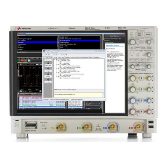
Keysight E6961A Compliance Solution Manuals
Manuals and User Guides for Keysight E6961A Compliance Solution. We have
1
Keysight E6961A Compliance Solution manual available for free PDF download: User Manual And Method Of Implementation
Keysight E6961A User Manual And Method Of Implementation (75 pages)
Automotive Ethernet Transmit Compliance Solution
Brand:
Keysight
| Category:
Test Equipment
| Size: 2 MB
Table of Contents
Table of Contents
3
Overview
9
Introduction
10
Installing the Compliance Test Solution Software
11
Installing the License Key
12
Preparing to Take Measurements
13
Calibrate the Oscilloscope
13
Two Oscilloscope Channels Connection to Oscilloscope
14
Single Differential Probe Connection to Oscilloscope
15
Figure 1-1 Connection to the Oscilloscope Using a Pair of SMA Cables
15
Figure 1-2 Connection to the Oscilloscope Using a Differential Probe
15
Figure 1-3 General Test Setup Using the N5395C Evaluation Board
16
Figure 1-4 Launching the Broadr-Reach Compliance Test
18
Starting the Automotive Ethernet Compliance Test Solution Software
18
Figure 1-6 Select Tests Menu with All Tests Selected
20
Figure 1-7 Configure Tab for Test Mode
22
Figure 1-8 Connect Tab for Test Mode
23
Tabs
24
Top Menu Bar
24
Test Mode 1. Output Droop Tests
25
Test Setup
25
Specification References
25
Transmitter Output Droop Positive Test Information
25
Transmitter Output Droop Negative Test Information
26
Figure 1-11 Typical Negative Droop Test Waveform (Using a Pair of SMA Cables)
27
Test Mode 2. MASTER Clock Frequency and Jitter Tests
28
Test Setup
28
Specification References
28
Transmit Clock Frequency (MASTER) Test Information
28
Figure 1-12 Typical MASTER Clock Test Waveform (Using a Pair of SMA Cables)
29
MASTER Txout Jitter Test Information
30
Figure 1-13 Typical MASTER TX out Test Waveform (Using a Pair of SMA Cables)
30
Test Mode 3. SLAVE Transmit Clock Frequency and Jitter Tests
31
Test Setup
31
Specification References
31
Transmit Clock Frequency (SLAVE) Test Information
31
Figure 1-14 Typical TX Test Waveform (Using a Pair of SMA Cables)
32
Figure 1-15 Typical TX-TCLK Test Waveform (Using a Pair of SMA Cables)
33
Test Mode 4. Transmitter Distortion and MDI Return Loss Tests
34
Test Setup
34
Figure 1-16 Transmitter Distortion Test Connection Using Two Keysight 33250A Function Generators
35
Figure 1-17 Connection for Transmitter Distortion Test Using Keysight
36
Using the Optional E6961A Frequency Divider Board
37
Specification References
37
Figure 1-18 Connection for Transmitter Distortion Test Using Keysight 81150A Function Generator
37
Transmitter Distortion Tests Information
38
Transmitter Distortion Enhance Clock Recovery Algorithm
38
Figure 1-19 Typical Distortion Test Waveform (Using a Pair of SMA Cables)
39
Figure 1-20 Connection Setup for MDI Return Loss Test
40
MDI Return Loss Test
40
Test Setup
40
MDI Return Loss Test Information
41
Test Mode 5. Transmitter Power Spectral Density (PSD) and Transmitter Peak Differential Output Tests
42
Test Setup
42
Specification References
43
PSD Test Information
43
Transmitter Peak Differential Output
44
Figure 1-22 Typical Spectral Density Loss Test Waveform
44
Viewing the Test Report
45
Figure 1-23 Typical Results Tab
45
Figure 1-24 Top Portion of a Typical HTML Report
46
Reference Documents
47
Other Keysight Automotive Ethernet Applications and Software
47
Setting up the N5395C Ethernet Transmitter Test Fixture
49
Introduction
50
Figure A-1 Return Loss Impedance Calibration Board
51
Figure A-2 N5395C Ethernet Electrical Transmitter Test Fixture
51
Jumper Settings
52
Configure External Instruments
55
Introduction
56
Figure B-1 Broadr-Reach Compliance Test Application Main Menu
56
Figure B-2 Broadr-Reach Compliance Test Application External Instruments List
57
External Instrument Calibration
59
Introduction
60
Calibrating the AWG
60
Figure C-1 AWG Calibration Setup for the Disturbing Signal Source
61
Calibrating the ENA
62
Figure C-2 Broadr-Reach Compliance Test Application Main Menu
62
Figure C-3 ENA Calibration Setup
63
Using the E6960-66600 Frequency Divider Board
65
Introduction
66
Figure D-1 Keysight's E6961A-FDB Frequency Divider Board
66
Static-Safe Handling Procedures
67
Figure D-2 Check the Use 10Mhz Ref Clock on Main Application
68
Figure D-3 Test Setup for 10 Mhz Frequency Reference
69
Frequency Divider Board Test Setup
69
Connector Description
70
DIP Switch Description
71
LED Description
73
Advertisement
Advertisement
Related Products
Keysight E6953A
Keysight E6610A
Keysight E6650A EXF
Keysight E6607B
Keysight E6640A
Keysight InfiniiVision EDUX1002G
Keysight EDUX1052G
Keysight Infiniium EXR258A
Keysight Infiniium EXR208A
Keysight Infiniium EXR054A
Keysight Categories
Measuring Instruments
Test Equipment
Multimeter
Portable Generator
Power Supply
More Keysight Manuals
Login
Sign In
OR
Sign in with Facebook
Sign in with Google
Upload manual
Upload from disk
Upload from URL