Sign In
Upload
Manuals
Brands
Keysight Manuals
Power Supply
E3632A
User Manuals: Keysight E3632A Bench Power Supply
Manuals and User Guides for Keysight E3632A Bench Power Supply. We have
2
Keysight E3632A Bench Power Supply manuals available for free PDF download: User Manual, Service Manual
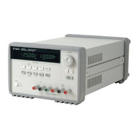
Keysight E3632A User Manual (196 pages)
Brand:
Keysight
| Category:
Power Supply
| Size: 2 MB
Table of Contents
DC Power Supply
1
Safety Notices
4
Safety Symbols
5
Safety Considerations
6
Environmental Conditions
8
Table of Contents
13
1 Getting Started
24
Introduction
24
Figure 1-1 Shorting Conductors Without Insulation
27
Standard Shipped Items
29
Options
29
Table 1-1 E3632A Options
29
Accessories
30
Table 1-2 E3632A Accessories
30
Preparing the Power Supply
31
Preliminary Checkout
31
Power-On Checkout
32
Checking the Output
33
Input Power Requirements
35
Rack-Mount the Power Supply
38
Product at a Glance
40
Front Panel
40
Figure 1-2 Front Panel
40
Table 1-3 Front Panel Overview
40
Figure 1-3 Voltage and Current Limit Settings
42
Rear Panel
43
Figure 1-4 Rear Panel
43
Table 1-4 Rear Panel Overview
43
Display Annunciators
44
Figure 1-5 Display Annunciators
44
Table 1-5 Display Annunciators Overview
44
Operating the Power Supply
46
Cooling
46
Bench Operation
46
Cleaning
46
2 Operation and Features
48
Overview
48
Constant Voltage Operation
50
Front Panel Operation
50
Remote Interface Operation
52
Constant Current Operation
52
Front Panel Operation
52
Remote Interface Operation
54
Storing and Recalling Operating States
55
Front Panel Operation
55
Remote Interface Operation
57
Programming the Overvoltage Protection
57
Front Panel Operation
57
Remote Interface Operation
59
Programming the Overcurrent Protection
60
Front Panel Operation
60
Figure 2-1 Recommended Protection Circuit for Battery
60
Remote Interface Operation
62
Remote Voltage Sensing
63
CV Regulation
63
Output Rating
64
Output Noise
64
Stability
64
Remote Voltage Sensing Connections
65
Figure 2-2 Remote Voltage Sensing Connections
65
Disabling the Output
66
Front Panel Operation
66
Remote Interface Operation
66
Disconnecting the Output Using an External Relay
67
Knob Locking
67
System-Related Operations
68
Self-Test
68
Error Conditions
69
Display Control
70
Firmware Revision Query
71
SCPI Language Version
71
Remote Interface Configuration
73
Remote Interface Selection
73
GPIB Address
74
Baud Rate Selection (RS-232)
74
Parity Selection (RS-232)
75
To Set the GPIB Address
75
To Set the Baud Rate and Parity (RS-232)
76
GPIB Interface Configuration
78
RS-232 Interface Configuration
79
RS-232 Configuration Overview
79
RS-232 Data Frame Format
80
Connection to a Computer or Terminal
80
Figure 2-3 RS-232 Data Frame Format
80
Figure 2-4 DB-9 Serial Connection
81
DTR/DSR Handshake Protocol
82
Figure 2-5 DB-25 Serial Connection
82
RS-232 Troubleshooting
84
Calibration
85
Calibration Security
85
To Unsecure for Calibration
86
To Secure against Calibration
87
To Change the Security Code
88
Calibration Count
89
Calibration Message
90
3 Remote Interface Reference
92
SCPI Command Summary
92
Table 3-1 SCPI Command Summary
93
Introduction to the SCPI Language
96
Command Format Used in this Manual
97
Command Separators
98
Using the MIN and MAX Parameters
99
Querying Parameter Settings
99
SCPI Command Terminators
100
IEEE-488.2 Common Commands
100
SCPI Parameter Types
100
Simplified Programming Overview
102
Using the Apply Command
102
Using the Low-Level Commands
102
Reading a Query Response
103
Selecting a Trigger Source
103
Power Supply Programming Ranges
104
Table 3-2 Keysight E3632A Programming Ranges
104
Using the Apply Command
105
Apply {<Voltage>| DEF | MIN | Max}[,{<Current>| DEF | MIN | MAX}]
105
Apply
106
Output Settings and Operation Commands
107
Triggering Commands
115
Trigger Source Choices
115
Triggering Commands
117
System-Related Commands
118
Table 3-3 Power Supply State
121
Calibration Commands
124
RS-232 Interface Commands
128
SCPI Status Registers
129
What Is an Event Register
129
What Is an Enable Register
129
SCPI Status System
130
Figure 3-1 SCPI Status System
130
The Questionable Status Register
131
Table 3-4 Bit Definitions - Questionable Status Register
131
The Standard Event Register
132
Table 3-5 Bit Definitions - Standard Event Register
132
The Status Byte Register
134
Table 3-6 Bit Definitions - Status Byte Summary Register
134
Using Service Request (SRQ) and Serial POLL
135
Using *STB? to Read the Status Byte
136
Using the Message Available Bit (MAV)
136
To Interrupt Your Bus Controller Using SRQ
137
To Determine When a Command Sequence Is Completed
137
Using *OPC to Signal When Data Is in the Output Buffer
138
Status Reporting Commands
139
Halting an Output in Progress
143
SCPI Conformance Information
144
SCPI Confirmed Commands
144
Table 3-7 SCPI Confirmed Commands
144
Device-Specific Commands
146
Table 3-8 Non-SCPI Commands
146
IEEE-488 Conformance Information
147
Dedicated Hardware Lines
147
Addressed Commands
147
IEEE-488.2 Common Commands
148
4 Error Messages
149
Overview
150
Front Panel Operation
150
Remote Interface Operation
151
Execution Error Messages
152
Table 4-1 Execution Error Messages
152
Self-Test Error Messages
157
Table 4-2 Self-Test Error Messages
157
Calibration Error Messages
159
Table 4-3 Calibration Error Messages
159
5 Application Programs
161
Overview
162
Example Program for C++ (GPIB IEEE 488)
163
Example Program for Excel 5.0 (Windows 3.1 and GPIB)
166
6 Tutorial
172
Overview of the Power Supply Operation
172
Figure 6-1 Diagram of a Simple Series Power Supply with Tap
172
Figure 6-2 Block Diagram of the Power Supply Showing the Remote Interface Isolation
173
Output Characteristics
174
Figure 6-3 Ideal Constant Voltage Power Supply
174
Figure 6-4 Ideal Constant Current Power Supply
174
Figure 6-5 Output Characteristics
175
Unregulated State
176
Unwanted Signals
176
Figure 6-6 Simplified Diagram of the Common Mode and Normal Mode Sources of Noise
178
Connecting the Load
179
Output Isolation
179
Multiple Loads
179
Remote Voltage Sensing
180
Table 6-1 Wire Rating
180
Load Consideration
181
Figure 6-7 Regulated Power Supply with Remote Sensing
181
Table 6-2 Slew Rate
182
Extending the Voltage Range and Current Range
184
Series Connections
184
Parallel Connections
185
Remote Programming
186
Figure 6-8 Speed of Response - Programming up (Full Load)
186
Figure 6-9 Speed of Response - Programming down
187
Reliability
188
7 Characteristics and Specifications
189
Physical Characteristics
190
Figure 7-1 E3632A Dimensions
190
Table 7-1 Physical Characteristics
190
Environmental Characteristics
191
Electrical Specifications
191
Table 7-2 Electrical Specifications
191
Supplemental Characteristics
193
Table 7-3 Supplemental Characteristics
193
Advertisement
Keysight E3632A Service Manual (73 pages)
Brand:
Keysight
| Category:
Power Supply
| Size: 1 MB
Table of Contents
DC Power Supply
1
Copyright Notice
2
Declaration of Conformity
2
Safety Information
2
Safety Symbols
3
Safety and EMC Requirements
4
Safety Considerations
4
Environmental Conditions
6
Regulatory Markings
7
Sales and Technical Support
8
Waste Electrical and Electronic Equipment (WEEE) Directive
8
Product Category
8
Table of Contents
9
Calibration Procedures
17
Closed-Case Electronic Calibration
18
Keysight Calibration Services
18
Calibration Interval
18
Automating Calibration Procedures
19
Recommended Test Equipment
20
Test Considerations
21
Performance Verification Tests
22
Self-Test
22
Measurement Techniques
23
Setup for most Tests
23
Electronic Load
24
Current-Monitoring Resistor
24
Programming
24
Constant Voltage (CV) Verifications
25
Constant Voltage Test Setup
25
Voltage Programming and Readback Accuracy
25
CV Load Regulation
26
CV Line Regulation
27
Normal Mode Voltage Noise (CV Ripple and Noise)
27
Load Transient Response Time
29
Constant Current (CC) Verifications
30
Constant Current Test Setup
30
Current Programming and Readback Accuracy
30
CC Load Regulation
31
CC Line Regulation
32
Normal Mode Current Noise (CC Ripple and Noise)
33
Common Mode Current Noise
34
Performance Test Record for E3632A
35
CV Performance Test Record
35
CC Performance Test Record
36
Calibration Security Code
37
To Unsecure the Power Supply for Calibration
38
To Unsecure the Power Supply Without the Security Code
39
Calibration Count
40
Calibration Message
40
General Calibration/Adjustment Procedure
41
Voltage and OVP Calibration
42
Current and OCP Calibration
44
Aborting a Calibration in Progress
47
Calibration Record for E3632A
48
Error Messages
49
System Error Messages
49
Self-Test Error Messages
50
Calibration Error Messages
51
Calibration Program
52
Service
57
Operating Checklist
58
Types of Service Available
59
Standard Repair Service (Worldwide)
59
Repacking for Shipment
59
Electrostatic Discharge (ESD) Precautions
60
Surface Mount Repair
60
To Replace the Power-Line Fuse
61
To Disconnect the Output Using an External Relay
61
Installation Procedure for an External Relay
62
Troubleshooting Hints
63
Unit Is Inoperative
63
Unit Reports Errors 740 to 750
63
Unit Fails Self-Test
63
Bias Supplies Problems
64
Self-Test Procedures
65
Power-On Self-Test
65
Complete Self-Test
65
Component Locator Diagram
69
Component Locator Diagram for the Main Board Assembly - Top
69
Component Locator Diagram for the Front Panel - Top
70
Component Locator Diagram for the Main Board Assembly - Top (Serial My53Xx6Xxx)
71
Component Locator Diagram for the Front Panel - Top (Serial My53Xx6Xxx)
72
Advertisement
Related Products
Keysight E3633A
Keysight E3634A
Keysight E3630A
Keysight E3631A
Keysight E36311A-0E9
Keysight E36312A-0EM
Keysight E36311A-0E3
Keysight E36312A-0E3
Keysight E36313A-0E9
Keysight E36313A-0EM
Keysight Categories
Measuring Instruments
Test Equipment
Multimeter
Portable Generator
Power Supply
More Keysight Manuals
Login
Sign In
OR
Sign in with Facebook
Sign in with Google
Upload manual
Upload from disk
Upload from URL