Sign In
Upload
Manuals
Brands
Keysight Manuals
Measuring Instruments
1912A
Keysight 1912A Manuals
Manuals and User Guides for Keysight 1912A. We have
1
Keysight 1912A manual available for free PDF download: User Manual
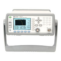
Keysight 1912A User Manual (287 pages)
P-Series Power Meters
Brand:
Keysight
| Category:
Measuring Instruments
| Size: 6.57 MB
Table of Contents
Declaration of Conformity
2
Certification
3
General Warranty
3
Warranty Service
3
Limitation of Warranty
4
Exclusive Remedies
4
Restricted Rights Legend
5
Technology Licenses
5
Safety Symbols
6
Safety Considerations
7
Recommended Calibration Interval
7
General Safety Information
8
Environmental Conditions
9
Regulatory Information
10
Safety Compliance
10
EMC Compliance
10
Regulatory Markings
11
Waste Electrical and Electronic Equipment (WEEE) Directive 2002/96/ EC
12
Product Category
12
Sales and Technical Support
12
Table of Contents
13
List of Figures
21
Safety Information
2
1 Introduction
29
LXI Class-C Compliant Power Meter
30
Rack Mounting
30
Power Meter and Sensor Capability
31
Specifications
31
Conventions Used in this Guide
32
Front Panel Keys and Connections
33
The Display Layout
38
Figure 1-1 Dual Numeric Display
38
Figure 1-2 Single Numeric and Analog Display
40
Figure 1-3 Full Screen Numeric Display
41
Figure 1-4 Trace Display in both Windows
42
Figure 1-5 Trace Display in Single Enlarged Window in Markers
43
Figure 1-6 Trace Display in Single Enlarged Window in Trigger Delay Mode
44
Figure 1-7 Trace Display in Single Enlarged Window in Trace Control
45
Window Symbols and Pop-Ups
46
Warning Symbol Pop-Up
46
Wait Symbol Pop-Up
47
Confirm Symbol Pop-Up
47
Numeric Entry Pop-Up
47
Text Entry Pop-Up
48
Trace Scaling Pop-Up
48
List Pop-Up
49
Using the Instrument Web Browser
50
Figure 1-8 Opening the Instrument Web Interface
50
Figure 1-9 N1912A P-Series Power Meter Web Browser (Welcome Page)
51
Figure 1-10 Status Message before Toggle ID Is Selected
52
Figure 1-11 Status Message When Toggle ID Is Selected
52
Figure 1-12 Example of Lan Status Message
53
Editing the Instrument's LAN Settings
54
Figure 1-13 Viewing LAN Configuration Settings from the Web
54
Figure 1-14 Password Security Dialog Box
55
Figure 1-15 Changing the Instrument LAN Interface Configuration
56
2 General Power Meter Functions
58
Setting the Units of Measurement
58
Selecting Units of Measurement from the Softkeys
59
Setting the Measurement Frequency
60
Procedure
60
Setting the Resolution
61
Making Relative Measurements
62
Procedure
62
Figure 2-2 Typical Relative Measurement Display
62
Figure 2-3 Numeric Display
63
Setting the Pulse Reference Levels
64
Figure 2-4 Measurement Configuration Screen
64
Figure 2-5 Pulse Duration Measurement between Two Reference Levels
65
Figure 2-6 Trace Ref Lvl 1 Pop-Up
65
Figure 2-7 Trace Ref Lvl 2 Pop-Up
66
Figure 2-8 Pulse Duration Ref Lvl Pop-Up
66
Setting Offsets
67
Figure 2-9 Simplified Measurement Path
67
Figure 2-10 Typical Channel Offset Display
68
Procedure
68
Setting Channel Offsets
68
Figure 2-11 Channel Offset Indicator
69
Figure 2-12 Typical Display Offset Display
70
Procedure
70
Setting Display Offsets
70
Setting Frequency Dependent Offsets
71
Figure 2-13 Frequency Dependent Offset Tables Display
73
Figure 2-14 Frequency Dependent Offset Indicator
73
Editing Frequency Dependent Offset Tables
74
Figure 2-15 "Edit Offset" Display with Data Added
75
Figure 2-16 Edit Table Title Pop-Up
76
Setting Measurement Averaging
78
Figure 2-17 Typical Averaged Readings
78
Figure 2-18 Meas Avg Count Pop-Up
79
Procedure
79
Step Detection
81
Procedure
81
Setting the Video Averaging
82
Procedure
82
Figure 2-19 Video Avg Count Pop-Up
83
Setting the Video Bandwidth
84
Procedure
85
Figure 2-20 Bandwidth Filter Shapes
85
Figure 2-21 Video Bandwidth Pop-Up
86
Setting Measurement Channel Gates
87
Figure 2-22 Example of Measurement Gates
87
Figure 2-23 Gate Setup Screen
88
Procedure
88
Figure 2-24 Time Gating Start Pop-Up
89
Figure 2-25 Time Gating Length Pop-Up
89
Auto Gate
90
Figure 2-26 Auto Gate Settings Display
90
Figure 2-27 Marker 1 Ref Percentage Pop-Up
90
Figure 2-28 Marker 2 Ref Percentage Pop-Up
91
Setting up the Channel Trace
92
Procedure
92
Figure 2-29 the Placement of Gates (Markers) in Auto Gating Mode 91 Figure 2-30 Trace Setup Display
92
Figure 2-31 Trace Start Time Pop-Up
93
Figure 2-32 X Scale/Division Pop-Up
93
Figure 2-33 Trace Units Pop-Up
94
Figure 2-34 y Scale Maximum Value Pop-Up
94
Auto Scale
95
Figure 2-35 y Scale/Division Pop-Up
95
Setting the Trigger
96
Figure 2-36 Trigger Menu - Free Run Mode
96
Figure 2-37 Trigger Setting Menu 1 of 2
97
Procedure
97
Figure 2-38 Trigger Level Pop-Up
99
Figure 2-39 Trigger Delay Pop-Up
99
Figure 2-40 Trigger Setting Menu 2 of 2
100
Figure 2-41 Trigger Holdoff Pop-Up
101
Figure 2-42 Trigger Hysteresis Pop-Up
102
Power Sweep Mode
104
Figure 2-43 TRIG in and TRIG out Connection Diagram between Power Meter and Power Source
105
Figure 2-44 Channel Setup Display
106
Figure 2-45 Sensor Mode Pop-Up
107
Figure 2-46 Trigger Setting Menu 1 of 2
108
Figure 2-47 Trigger Setting Menu 2 of 2
108
Frequency Sweep Mode
112
Determine the Right Step to be Set
117
Setting Measurement Limits
118
Figure 2-48 Limits Checking Applications
118
Figure 2-49 Limits Checking Results
118
Setting Limits
119
Figure 2-50 Minimum Limit Pop-Up
120
Checking for Limit Failures
121
Figure 2-51 Limit Failures
121
Setting the Measurement Display
122
Figure 2-52 Sixteen Measurements Per Channel
122
Figure 2-53 Measurement Feed Example
123
Numeric Format
124
Single Function Measurement
125
Figure 2-56 Measurement Type Pop-Up
126
Figure 2-57 Gating Number Pop-Up
126
Combined Measurement
127
Figure 2-59 Measurement Example Display
128
Scaling the Analog Display
129
Figure 2-60 Maximum Limit Pop-Up
129
Figure 2-61 Minimum Limit Pop-Up
130
Figure 2-62 Increment and Decrement Multiplier
130
Recorder Output
131
Procedure
131
Figure 2-63 Recorder Minimum Pop-Up
132
Figure 2-64 Recorder Maximum Pop-Up
132
Figure 2-65 Increment and Decrement Multiplier
134
N1911A/N1912A Option H01
135
Figure 2-66 Measurement Example for Option H01
135
Figure 2-67 Example Screenshot of the RF Multitone Waveform
136
Saving and Recalling Power Meter States
137
Editing a Register's Name
138
Figure 2-69 Save Confirm Pop-Up
138
Figure 2-70 File Name Pop-Up
138
Recalling a Measurement Setup
139
Figure 2-71 Recall Pop-Up
139
Zeroing and Calibrating the P-Series Sensor
140
Zeroing
140
Figure 2-72 Zeroing Pop-Up
140
Calibration
141
Figure 2-73 Calibration Wait Pop-Up
142
Manual Calibration
142
Zero/Cal Lockout
143
Figure 2-74 Please Zero and Calibrate Window
143
Presetting the Power Meter
145
Figure 2-75 Preset Display Options
145
Setting the Cable Short/Long
147
Short
147
Long
147
Figure 2-76 Short/Long Cable Option
147
3 Using P-Series Power Sensor
150
Introduction
150
Configuring a Power Measurement
151
Setting the Trace Display
152
Step 1. Connecting the Power Sensor
153
Step 2. Setting the Channel Frequency
153
Figure 3-1 P-Series Sensor Default Channel Setup
153
Step 3. Setting the Trigger
154
Step 4. Setting the Display to Trace
154
Figure 3-2 Trace Display in Dual Channel Power Meter
154
Step 5. Expanding the Trace Display
155
Figure 3-3 Trace Display in Single Enlarged Window
155
Gate Control in a Single Enlarged Window
156
Figure 3-4 Trace Display with Gate Control Menu
156
Figure 3-5 Trace Display with Trigger Delay Menu
158
Figure 3-6 Trace Display with Trace Control Menu
159
Viewing the Results in a Full Screen Window
160
Figure 3-7 Trace Display in Full Screen
161
Improving the Accuracy with Additional Settings
162
Figure 3-8 P-Series Power Sensor Default Channel Setup
162
Figure 3-9 Channel Offset Display
163
4 Using E9320 E-Series Power Sensors
166
Introduction
166
Figure 4-1 Bandwidth Filter Shapes
167
Power Meter Configuration
168
Default Channel Setup
168
Figure 4-2 E-Series E9320 Power Sensor Default Channel Setup
168
Configuring a Peak Power Measurement
169
Measurement Accuracy
170
Procedure
170
Figure 4-3 Frequency Pop-Up
171
Setting the Trace Display
172
Step 1. Connecting the Power Sensor
173
Step 2. Setting the Channel Frequency
173
Step 3. Setting the Trigger
173
Step 4. Setting the Display to Trace
174
Figure 4-4 E-Series E9320 Power Sensor Channel Setup When Trigger Is Selected
174
Figure 4-5 Trace Display in Dual Channel Power Meter
174
Step 5. Expanding the Trace Display
175
Figure 4-6 Trace Display in Single Enlarged Window
175
Gate Control in a Single Enlarged Window
176
Figure 4-7 Trace Display with Gate Control Menu
176
Figure 4-8 Trace Display with Trigger Delay Menu
177
Figure 4-9 Trace Display with Trace Control Menu
179
Viewing the Results in a Full Screen Window
180
Figure 4-10 Trace Display in Full Screen
180
Improving the Accuracy with Additional Settings
181
Figure 4-12 Channel Offset Display
182
5 Using E9300 E-Series Power Sensors
186
Introduction
186
Power Meter Configuration
187
Figure 5-1 E9300 E-Series Auto-Averaging Settings
187
Default Channel Setup
188
Measurement Accuracy
189
Procedure
190
Measuring Spread Spectrum and Multitone Signals
192
Figure 5-4 Spread Spectrum Signal
192
CDMA Signal Measurements
193
Figure 5-6 CDMA (IS-95A): 9Ch Fwd
193
Figure 5-7 Calibration Factors Versus Frequency
194
Multitone Signal Measurements
194
Measuring TDMA Signals
195
Power Meter and Sensor Operation
195
Achieving Stable Results with TDMA Signals
195
Achieving Stable Results with GSM Signals
196
Electromagnetic Compatibility (EMC) Measurements
197
Measurement Accuracy and Speed
198
Setting the Range
198
Measurement Considerations
199
6 Using E4410 E-Series Power Sensors Introduction
202
Power Meter Configuration
203
Figure 6-1 E-Series CW Sensor Auto-Averaging Settings
203
Default Channel Setup
204
Figure 6-2 E-Series E4410 Sensor Default Channel Setup
204
Measurement Accuracy
205
Procedure
205
Figure 6-3 Frequency Pop-Up
206
7 Using 8480 Series Power Sensors
208
Introduction
208
Using 8480 Series Power Sensors Introduction
208
Power Meter Configuration
209
Figure 7-1 8480 Series Auto-Averaging Settings
209
8480 Series Sensors Connection Requirements
210
Default Channel Setup
210
Figure 7-2 8480 Series Sensor Default Channel Setup
210
Measurement Accuracy
212
Frequency Specific Calibration Factors
213
Procedure
213
Figure 7-3 Reference Calibration Factor Pop-Up Window
214
Figure 7-4 Calibration Factor Pop-Up Window
215
Figure 7-5 Calibration Factor Display
215
Sensor Calibration Tables
217
Procedure
218
Figure 7-6 Sensor Table Selected
218
Figure 7-7 Frequency Dependent Offset Indicator
219
Figure 7-8 Frequency/Calibration Table Display
220
Editing/Generating Sensor Calibration Tables
221
Figure 7-9 "Sensor Tbls" Screen
222
Figure 7-10 "Edit Cal" Display
223
Figure 7-11 Edit Table Title Pop-Up
223
Pre-Installed Calibration Table Contents
225
Figure 5-2
226
8 Using N8480 Series Power Sensors
230
Introduction
230
Using N8480 Series Power Sensors
231
Power Meter Configuration Changes
232
Figure 8-1 Auto-Averaging Settings
232
Default Channel Setup
233
Figure 8-2 N8480 Series Sensor (Excluding Option CFT) Default Channel Setup
233
Figure 8-3 N8480 Series Sensor with Option CFT Default Channel
233
N8480 Series Sensors Connection Requirements
234
N8480 Series Power Sensors (Excluding Option CFT)
235
Procedure
235
Figure 8-4 Frequency Pop-Up
236
N8480 Series Power Sensors with Option CFT
237
Frequency Specific Calibration Factors
237
Figure 8-5 Reference Calibration Factor Pop-Up Window
238
Figure 8-6 Calibration Factor Pop-Up Window
239
Figure 8-7 Calibration Factor Displayed
240
Sensor Calibration Tables
242
Selecting a Sensor Calibration Table
243
Figure 8-8 Sensor Table Selected
244
Figure 8-9 Frequency Dependent Offset Indicator
244
Figure 8-10 Frequency/Calibration Table Display
245
Editing/Generating Sensor Calibration Tables
246
Figure 8-11 "Sensor Tbls" Screen
247
Figure 8-12 "Edit Cal" Display
248
Figure 8-13 Edit Table Title Pop-Up
248
9 Complementary Cumulative Distribution Function (CCDF)
252
Introduction
252
Setting the CCDF Table
253
Windowed CCDF Table
253
Figure 9-1 CCDF Table in Windowed Display
253
Expanded CCDF Table
254
Figure 9-2 CCDF Table in Expanded Display
254
Full Screen CCDF Table
255
Figure 9-3 CCDF Table in Full-Screen Display
255
Setting the CCDF Trace
256
Figure 9-4 Trace Display Select Control Menu
256
Figure 9-5 CCDF Trace Display with Marker Trace Menu
257
Figure 9-6 Scale/DIV Pop-Up
259
Figure 9-7 Selection of CCDF Trace to be Stored as a Reference
259
10 Maintenance
261
Self Test
262
Power on Self Test
262
Front Panel Selection of Self Tests
262
Instrument Self Test
263
Figure 10-1 Self Test Complete
263
Remote Testing
264
Test Descriptions
264
Error Messages
266
Introduction
266
Error Message List
268
Operator Maintenance
275
Replacing the Power Line Fuse
275
Figure 10-3 Replacing the Fuse
276
Contacting Keysight Technologies
277
Before Calling Keysight Technologies
277
Check the Basics
277
Instrument Serial Numbers
278
Erasing Memory Data
280
Returning Your Power Meter for Service
281
Packaging the Power Meter for Shipment
281
Advertisement
Advertisement
Related Products
Keysight 1914A
Keysight 16801A
Keysight 16802A
Keysight 16803A
Keysight 16804A
Keysight 16806A
Keysight 16863A
Keysight 16862A
Keysight 16864A
Keysight 1146B
Keysight Categories
Measuring Instruments
Test Equipment
Multimeter
Control Unit
Portable Generator
More Keysight Manuals
Login
Sign In
OR
Sign in with Facebook
Sign in with Google
Upload manual
Upload from disk
Upload from URL