Sign In
Upload
Manuals
Brands
Keithley Manuals
Measuring Instruments
237
Keithley 237 Manuals
Manuals and User Guides for Keithley 237. We have
3
Keithley 237 manuals available for free PDF download: Applications Manual, Service Manual, Instruction Manual
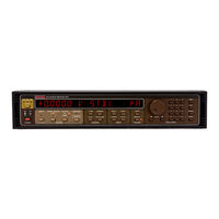
Keithley 237 Service Manual (138 pages)
Source Measure Unit and High Voltage Source Measure Unit
Brand:
Keithley
| Category:
Measuring Instruments
| Size: 36 MB
Table of Contents
Table of Contents
21
Performance Verification
27
Introduction
27
Environmental Conditions
27
Initial Cond1Tions
27
Required Test Equtpment
28
Verifications Procedures
28
Equipment Characterization
30
Table 1-3 Model 263 I-Source Characteristics
31
Common Mode Verification
32
Figure 1-2 Setup for Common Mode Verification
33
Voltage Source Verification
34
Figure 1-3 Setup for Voltage Source Ranges Verification
35
Voltage Measure Verification
35
Figure 1-4. Setupfor Voltagemeasure Ranges Verification
36
Table 1-5 Voltage Measure Verification
37
Remote Sense Verification
37
Figure 1-5 Setup for Remote Sense Verification
38
Low Current (Ina to Loma) Measure Ranges Verification
38
Low Current (Ina to Loma) Source Ranges Verification
43
Looma Measure Range Verification
44
Figure 1-8 Setup for Looma Measure Range Verification
45
Looma Source Range Verification
46
Calibration
49
Introduction
49
Recommended Calibration Equipment
49
Environmental Conditions
50
Warmup Period
50
Cal Lock
50
Calibration Procedures
50
Equipment Characterization
51
Figure 2-2 Setup for Equipment Characterization
52
Table 2-3 Model 263 I-Source Characterization
53
Voltage Calibration
54
Figure 2-3 Setup for Volts Calibration
55
Looma Range Calibration
57
Low Current Ranges Calibration (Ina Loma)
59
Calibration Errors
61
Table 2-4 Calibration Error Messages
62
Calibration Program
64
Table 3-1 Line Fuse Selection
73
Introduction
73
Line Fuse Replacement
73
Fan Filter Cleaning
73
Handling and Cleaning Precautions
76
Disassembly Instructions
76
Figure 3-3 Resonant Converter Board (Model 237)
77
Figure 3-4 Output Board
78
Figure 3-5 Analog Board (Shields Removed)
79
Diagnostics
82
Table 3-2 Recommended Troubleshooting Equipment
82
Special Handling of Static Sensitive Devices
82
Recommended Test Equipment
82
Power Supply Checks
84
Table 3-3 Power Supply Checks
84
Analog Switching
85
Table 3-4 Analog Switching; Current Ranging
85
Table 3-5 Analog Switching; Volts Ranging
86
Table 3-6 Analog Switching; Feedback
86
Digital and Display Checks
87
Table 3-9 Digital Circuitry Checks
88
Table 3-10 Display Circuitry Checks
89
Principles of Operation
90
Introduction
90
Analog Circuitry
91
V/I Control and Readback
91
Output Stage
93
Figure 4-3 Model 236 Output Stage (Simplified Schematic Diagram)
94
Feedback
95
Figure 4-6 Damping Relay Contact Bounce
96
Resonant Converter (Model 237)
97
A/D Converter
97
Table 4-1 Volts Range Relays
97
Digital Circuttry
98
I/O Controller
98
Source/Measure Controller
99
Communications
99
A Display Circuitry
99
Powersupply
100
Introduction
102
Parts Lists
102
Ordering Information
102
Schematic Diagrams and Component Location Drawings
102
Advertisement
Keithley
7012-S
Instruction Manual
Keithley 237 Instruction Manual (93 pages)
4x10 Matrix Card
Brand:
Keithley
| Category:
Test Equipment
| Size: 4 MB
Table of Contents
Table of Contents
10
Introduction
15
Features
15
Warranty Information
16
Manual Addenda
16
Safety Symbols and Terms
16
Specifications
16
Unpacking and Inspection
16
Inspection for Damage
16
Shipping Contents
16
Instruction Manual
17
Repacking for Shipment
17
Optional Accessories
17
Figure
18
Model 7012 Simplified Schematic
18
Figure
19
Model 7001 Analog Backplane
19
Introduction
18
Basic Matrix Configuration (4 × 10)
18
Figure
20
Single-Ended Switching Example
20
Matrix Row Connections to Backplane
20
Typical Matrix Switching Schemes
20
Single-Ended Switching
20
Differential Switching Example
21
Figure
21
Figure 2-6 Sensing Example
21
Differential Switching
21
Sensing
21
Figure 2-7 SMU Connections
22
SMU Connections
22
Matrix Expansion
22
Two-Card Switching Systems
22
Two Separate 4 × 10 Matrices
23
Figure
23
Figure
24
Narrow Matrix Example (4 × 20)
24
Figure 2-10 Wide Matrix Example (8 × 10)
25
Figure 2-11 Mixed Card Type Example
26
Mainframe Matrix Expansion
26
Introduction
28
Handling Precautions
28
Connections
28
Figure
29
Figure 3-1 Backplane Row Jumpers
29
Figure
30
Typical Terminal Block Connections
30
Backplane Row Jumpers
29
Screw Terminal Connector Card
29
Multi-Pin (Mass Termination) Connector Card
31
Cable Clamp for Screw Terminal Connector Card
31
Figure
31
Multi-Pin Connector Card Terminal Identification
32
Figure
32
Typical Round Cable Connection Techniques
34
Figure
34
Model 7011-MTR Connector Pinout
35
Figure
35
Model 7011-KIT-R (with Cable) Assembly
35
Typical Connection Schemes
36
Single Card System
36
Two-Card System
36
Single Card System Example (Multi-Pin Connector Card)
37
Two-Mainframe System
41
Model 7012 Installation and Removal
41
Figure
42
Introduction
47
Power Limits
47
Mainframe Control of Matrix Card
47
Channel Assignments
48
Channel Status Display
48
Figure
48
Display Organization for Multiplexer Channels
49
Figure
49
Model 7012 Programming Channel Assignments
49
Front Panel Control
50
IEEE-488 Bus Operation
50
Matrix Switching Examples
51
Thick Film Resistor Network Testing
51
Figure
52
Four-Terminal Ohms Measurements
52
Figure
53
Voltage Divider Checks
54
Transistor Testing
56
Figure 4-7 Transistor Testing
56
Figure 4-8 DC Parameter Checks
58
Measurement Considerations
59
Path Isolation
59
Magnetic Fields
60
Radio Frequency Interference
60
Ground Loops
60
Keeping Connectors Clean
61
AC Frequency Response
61
Introduction
63
Handling and Cleaning Precautions
63
Performance Verification
64
Environmental Conditions
64
Recommended Equipment
64
Verification Equipment
64
Matrix Card Connections
65
Channel Resistance Tests
65
Offset Current Tests
66
Contact Potential Tests
68
Path Isolation Tests
69
Differential and Common-Mode Isolation Tests
71
Special Handling of Static-Sensitive Devices
73
Differential and Common-Mode Isolation Testing
73
Principles of Operation
74
Block Diagram
74
ID Data Circuits
75
Relay Control
75
Relay Power Control
76
Power-On Safeguard
76
Troubleshooting
77
Troubleshooting Equipment
77
Troubleshooting Access
77
Troubleshooting Procedure
77
Recommended Troubleshooting Equipment
77
Table
77
Introduction
79
Parts Lists
79
Ordering Information
79
Factory Service
79
Component Layouts and Schematic Diagrams
80
Keithley 237 Applications Manual (201 pages)
Source Measure Unit
Brand:
Keithley
| Category:
Measuring Instruments
| Size: 13 MB
Advertisement
Advertisement
Related Products
Keithley 236
Keithley 238
Keithley SourceMeter 2611
Keithley 2612B
Keithley 2636
Keithley 2635
Keithley TEC SourceMeter 2510-AT
Keithley SourceMeter 2400
Keithley SourceMeter 2420
Keithley SourceMeter 2425
Keithley Categories
Measuring Instruments
Multimeter
Test Equipment
Power Supply
Switch
More Keithley Manuals
Login
Sign In
OR
Sign in with Facebook
Sign in with Google
Upload manual
Upload from disk
Upload from URL