Sign In
Upload
Manuals
Brands
Katronic Technologies Manuals
Measuring Instruments
FLUXUS ADM 6725
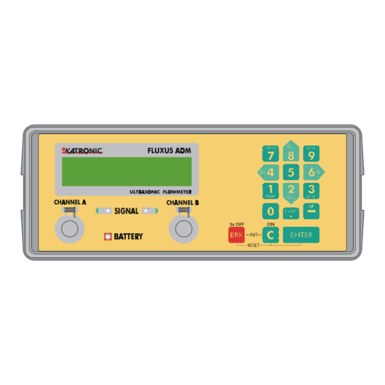
Katronic Technologies FLUXUS ADM 6725 Manuals
Manuals and User Guides for Katronic Technologies FLUXUS ADM 6725. We have
1
Katronic Technologies FLUXUS ADM 6725 manual available for free PDF download: Operating Instruction
Katronic Technologies FLUXUS ADM 6725 Operating Instruction (148 pages)
PORTABLE ULTRASONIC FLOWMETER
Brand:
Katronic Technologies
| Category:
Measuring Instruments
| Size: 1.35 MB
Table of Contents
Operating Instructions
1
Table of Contents
5
Overview
9
1 Functional Description
11
Measuring Principle
11
Operating Conditions for FLUXUS
11
2 Description of Flowmeter
15
Scope of Supply, Unpacking, Storage
15
Basic Instrument
16
Front Panel
16
Rear Panel
16
Transducers
17
Instrument Start-Up Basics
18
Switching ON/OFF, MAIN MENU
18
Selecting/Changing Languages
19
Hotcodes
20
Keyboard
21
General Functions
22
Displays
25
Types of Display Templates
25
Power Supply
26
Switch-Off Automatic
26
Battery Handling
27
3 Selection of the Measuring Point
29
Acoustic Propagation
29
Undisturbed Flow Profile
29
Examples for the Selection of the Measuring Point
29
Distances between Measuring Point and Disturbance Source
30
4 Program Branch PARAMETER
33
Program Branch PAR Overview
34
Input of Pipe Parameters
35
Outside Pipe Diameter / Circumference
35
Wall Thickness
36
Pipe Material
36
Pipe Lining
37
Pipe Roughness
38
Input of Medium Parameters
39
Sound Velocity
40
Kinematic Viscosity
40
Density
40
Medium Temperature
41
Input of the Transducer Parameters
41
5 Program Branch MEASURING
43
Program Branch MEA Overview
43
Measurement Preparation
45
Identification of the Measuring Point
46
Decide Which Sound Path to Use
46
Transducer Installation in Reflection Mode
47
Transducer Installation in Diagonal Mode
48
Transducer Distance
48
Cleaning of Outside Pipewall
49
Transducer Mounting
49
With Chains
49
With Tension Strap
50
With a Sensor Positioning Rail
51
Positioning of the Transducers
52
Start of the Measurement
53
Auto-Mux
53
Manual-Mux
53
Volume Flow
53
Recognition of Flow Direction
54
Cut-Off Flow
54
Flow Totalisers
55
Disturbances During Measurement
56
Operational Modes to Set-Up
57
Uncorrected Flow Velocity
57
Storage Mode
58
Total Quantity Storage
59
6 Program Branch Output Options
61
Program Branch OPT Overview
62
Selection of the Quantity and the Unit of Measurement
63
Quantity of Measurement: Volume Flow
63
Quantity of Measurement: Flow Velocity
64
Quantity of Measurement: Mass Flow
64
Quantity of Measurement: Heatflow
64
Activating of Temperature Channels
65
Set-Up of the Damping Factor
66
Storage of Measured Values with Internal Data Logger
66
Output of Measured Values Via Serial Interface
67
Set-Up of the Storage Interval
68
7 Program Branch SPECIAL FUNCTIONS
71
Program Branch SF Overview
72
Working with Parameter Records
74
Save Current Parameter Record
74
Selection of Parameter Records
75
Deletion of Parameter Records
76
Printing of Measured Values
76
Deletion of Measured Values
77
Selection of the Measuring Rate
78
Battery Charging
78
Clock Function
79
Set Date
79
Set Time
80
Installation/Deletion of User Defined Material
81
Installing/Renaming
81
Deleting
82
Installation/Deletion of User Defined Media
83
Installing/Renaming
83
Deleting
85
Instrument Information
86
8 Measuring Data Transfer
87
Utility Program MOVEFAST
88
Utility Program Flxtotxt
88
Utility Program MOVEDATA
90
Program Information and Error Messages
90
Adm 6725 E10 Kat
90
Format of the ASCII-File
91
9 Super User Mode
95
Activation/Deactivation of the Super User Mode
95
Decide Which Sound Path to Use
96
Transducer Parameters in Super User Mode
97
Malfunctions During Super User Mode
97
10 Virtual Calculation Channels
99
Overview
99
Characteristics of the Calculation Channels
99
Parameterisation of the Calculation Channels
100
Program Branch Output Options for a Calculation Channel
100
Measuring with Calculation Channels
102
Process Outputs from the Calculation Channels
102
11 Heat Quantity Measurement (HQM)
105
Overview of the HQM Option
105
Instrument
106
Extension of Program Branch MEASURING
106
Installation of the Temperature Sensors on the Pipe
107
During the Positioning Procedure for the Transducers
108
During Measuring
109
Correction of the Temperature Channels
110
Enabling or Disabling the Offset Correction
110
Input of the Correction Offsets
111
12 Wall Thickness Measurement (WTM)
113
Overview of the WTM Option
113
Instrument
113
Change to Operational Mode WTM
114
WTM Program Branch PARAMETER
114
Parameter Input for the Determination of the Wall
114
Thickness
114
WTM Program Branch MEASURING
115
Velocity 12.5 WTM Program Branch MEASURING
115
Measurement of the Wall Thickness
116
Further Information When Measuring
117
Measurement of the Sound Velocity
117
Measurement Failure
118
Stop Wall Thickness Measurement
119
Storage and Transfer of Thickness Value
119
Conventions When in Super User Mode
120
Program Branch WTM-OUTPUT OPTIONS
120
Set-Up of the Measuring Quantity
120
Set-Up of Other Output Options
120
13 Process Interfaces
123
Set-Up of Analogue Outputs
123
Decision on Error-Value and Error-Value Delay
123
Set-Up of Current Loop
125
Set-Up of Voltage Output
125
Set-Up of Frequency Output
125
Set-Up of the Full-Scale Value for All Analogue Outputs
125
Set-Up of Pulse Output
126
Set-Up of Alarm Outputs
126
Set-Up of Alarm Properties
128
Set-Up of the Limit Values
128
Apparent Delays When Switching Alarm Outputs
129
Cold Start
129
Disabling of Alarm Outputs
129
Alarm Outputs During Transducer Positioning
130
Limit Comparison with the Measured Value
130
Limit Comparison for Total Flow Quantity
130
Alarm Output Operation and Update
130
14 Errors
133
Error Messages
133
Errors During Parameter Input
133
Errors During Measurement
134
Errors During Data Transfer of Measured Values
135
Errors During Input of Programming Code
136
System Errors
136
Troubleshooting
137
Measurement Is Not Successful
137
Measurements Differ from the Expected Value
137
15 Maintenance, Service
139
16 Technical Data
141
Measuring Instrument
141
Clamp-On Flow Transducers
141
Mains Power Adapter and Battery Charging Unit
141
Units of Measurement
141
Transfer of Measured Values
141
Measuring Characteristics
142
Process Interfaces (Optional)
142
Wall Thickness Measurement (Optional)
142
Wall Thickness Probe DA301, HT400
142
Heat Quantity Measurement (Optional)
143
Integrated Measuring Point Multiplexer
143
Flow Nomogram
144
Adm 6725 E10 Kat
144
Advertisement
Advertisement
Related Products
Katronic Technologies KATflow 150
Katronic Technologies KATflow 200
Katronic Technologies KATflow 210
Katronic Technologies KATflow 230
Katronic Technologies Categories
Measuring Instruments
Transmitter
More Katronic Technologies Manuals
Login
Sign In
OR
Sign in with Facebook
Sign in with Google
Upload manual
Upload from disk
Upload from URL