Sign In
Upload
Manuals
Brands
JVC Manuals
Measuring Instruments
HR-VP690U
JVC HR-VP690U Manuals
Manuals and User Guides for JVC HR-VP690U. We have
1
JVC HR-VP690U manual available for free PDF download: Service Manual
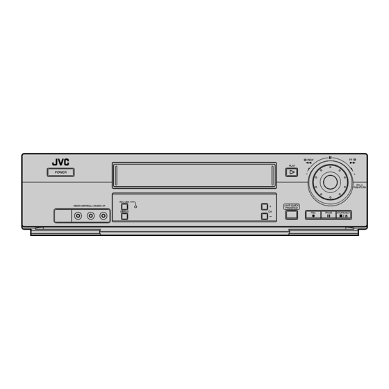
JVC HR-VP690U Service Manual (63 pages)
VIDEO CASSETTE RECORDER
Brand:
JVC
| Category:
Measuring Instruments
| Size: 5.19 MB
Table of Contents
Table of Contents
2
Important Safety Precautions
3
Disassembly
6
Disassembly Flow Chart
6
How to Read the Disassembly and Assembly
6
Disassembly/Assembly Method
6
Service Position
9
How to Set the "Service Position
9
Mechanism Service Mode
9
How to Set the "Mechanism Service Mode
9
Jig RCU Mode
9
Setting the Jig RCU Mode
9
Setting the User RCU Mode
9
Emergency Display Function
10
Displaying the EMG Information
10
Clearing the EMG History
10
EMG Content Description
11
EMG Detail Information <1
12
EMG Detail Information <2
13
Mechanism Adjustment
14
Before Starting Repair and Adjustment
14
Precautions
14
Checking for Proper Mechanical Operations
14
Manually Removing the Cassette Tape
14
Jigs and Tools Required for Adjustment
15
Maintenance and Inspection
16
Replacement of Major Parts
19
Before Starting Disassembling (Phase Matching between Mechanical Parts)
19
How to Set the "Mechanism Assembling Mode
19
Cassette Holder Assembly
19
Pinch Roller Arm Assembly
21
Guide Arm Assembly and Press Lever Assembly
21
A/C Head
21
Loading Motor
21
Capstan Motor
22
Pole Base Assembly (Supply or Take-Up Side)
22
Rotary Encoder
23
Clutch Unit
23
Change Lever Assembly, Direct Gear, Clutch Gear and Coupling Gear
23
Link Lever
24
Cassette Gear, Control Cam and Worm Gear
24
Control Plate
24
Loading Arm Gear (Supply or Take-Up Side) and Loading Arm Gear Shaft
25
Take-Up Lever, Take-Up Head and Control Plate Guide
26
Capstan Brake Assembly
26
Sub Brake Assembly (Take-Up Side)
26
Main Brake Assembly (Take-Up Side), Reel Disk (Take-Up Side) and Main Brake Assembly (Supply Side)
26
Tension Brake Assembly, Reel Disk (Supply Side) and Tension Arm Assembly
27
Idler Lever, Idler Arm Assembly
27
Stator Assembly
27
Rotor Assembly
27
Upper Drum Assembly
28
Compatibility Adjustment
29
FM Waveform Linearity
29
Height and Tilt of the A/C Head
30
A/C Head Phase (X-Value)
30
Standard Tracking Preset
31
Tension Pole Position
31
Electrical Adjustment
33
Precaution
33
Required Test Equipments
33
Required Adjustment Tools
33
Color (Colour) Bar Signal, Color (Colour) Bar Pattern
33
Switch Settings and Standard Precautions
33
Servo Circuit
34
Switching Point
34
Slow Tracking Preset
34
Video Circuit
34
Auto Picture Initial Setting
34
Demodulator Circuit
34
Separation
34
Charts and Diagrams
35
Notes of Schematic Diagram
35
Circuit Board Notes
36
Board Interconnections
37
Main (Video/Audio) Schematic Diagram
38
Main (Syscon) Schematic Diagram
39
Main (Sw. Reg) Schematic Diagram
40
Main (Tuner) Schematic Diagram
41
Main (Fma/Demod) Schematic Diagram
42
Main (Front) and Mini Front Schematic Diagrams
43
Main (Terminal) Schematic Diagram
44
Adv. Jog Schematic Diagram [Hr-Vp790U]
44
Connection Schematic Diagram
45
Main Circuit Board
46
Remote Controller Schematic Diagram
47
Fdp Grid Assignment and Anode Connection
48
Waveforms
48
Voltage Charts
49
Cpu Pin Function
49
System Control Block Diagram
50
Video Block Diagram
51
Audio Block Diagram
52
Parts List
53
Packing and Accessory Assembly <M1
53
Final Assembly M2
55
Mechanism Assembly M4
57
Electrical Parts List
58
Main Board Assembly <03
58
A/C Head Board Assembly <12
63
Mini Front Board Asseembly(Hr-Vp690U/U(C))<28
63
Adv.jog Board Asseembly(Hr-Vp790U/U(C))<38
63
Loading Motor Board Assembly <55
63
C.box/R.pause Board Assembly(Hr-Vp790U/U(C)<99
63
Advertisement
Advertisement
Related Products
JVC HM-DB1U
JVC HR-S9850MS
JVC HR-VP693U
JVC HR-VP653U
JVC HR-VP636U(C)
JVC HR-VP638U
JVC HR-VP644U(C)
JVC HR-VP674U
JVC HR-VP675U
JVC HR-VP636U
JVC Categories
Car Receiver
Camcorder
TV
VCR
Stereo System
More JVC Manuals
Login
Sign In
OR
Sign in with Facebook
Sign in with Google
Upload manual
Upload from disk
Upload from URL