Sign In
Upload
Manuals
Brands
Juniper Manuals
Network Hardware
QFX3000
User Manuals: Juniper QFX3000 Switch Networking
Manuals and User Guides for Juniper QFX3000 Switch Networking. We have
1
Juniper QFX3000 Switch Networking manual available for free PDF download: Manual
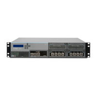
Juniper QFX3000 Manual (472 pages)
Brand:
Juniper
| Category:
Network Hardware
| Size: 10 MB
Table of Contents
Table of Contents
3
About the Documentation
23
Documentation and Release Notes
23
Supported Platforms
23
Documentation Conventions
23
Table 1: Notice Icons
24
Table 2: Text and Syntax Conventions
24
Documentation Feedback
25
Requesting Technical Support
25
About the Documentation
25
Self-Help Online Tools and Resources
26
Opening a Case with JTAC
26
Chapter 1 QFX3000 Qfabric Switch Overview
27
Chapter 2 QFX3100 Overview
27
QFX3500 Overview
27
QFX3000 Qfabric Switch Overview
29
Qfabric System Overview
29
Legacy Data Center Architecture
29
Figure 1: Legacy Data Center Architecture
30
QFX Series Qfabric System Architecture
31
Figure 2: QFX Series Qfabric System Architecture
31
Understanding the Qfabric System Hardware Architecture
33
Qfabric System Hardware Architecture Overview
33
Figure 3: Qfabric System Hardware Architecture
33
QFX3000 Qfabric Switch Overview
33
Qfabric System Features
35
Table 3: Supported Qfabric System Hardware Configurations
35
Understanding QFX3000-G Qfabric System Hardware Configurations
36
Understanding the Director Group
37
Director Group Components
37
Director Group Services
38
Understanding Routing Engines in the Qfabric System
38
Hardware-Based Routing Engines
39
Software-Based External Routing Engines
39
Figure 4: External Routing Engine Types
39
Understanding Interconnect Devices
40
Interconnect Device Introduction
40
QFX3008-I Interconnect Devices
41
Figure 5: Clos Switching for Interconnect Devices
41
Figure 6: QFX3008-I Data Plane and Control Plane Connections
42
Understanding Node Devices
43
Node Device Introduction
43
QFX3500 Node Devices
43
Figure 7: QFX3500 Data Plane and Control Plane Connections
44
Understanding Node Groups
45
Network Node Groups
45
Server Node Groups
45
QFX3100 Overview
47
QFX3100 Director Device Overview
47
Software
48
Physical Specifications
48
Network Modules
48
Figure 8: QFX3100 Director Device Front
48
Figure 9: QFX3100 Director Device Rear
48
Hard Disk Drive Modules
49
AC Power Supplies
49
Fan Modules
49
Field-Replaceable Units in a QFX3100 Director Device
49
QFX3100 Overview
49
Functionality
50
QFX3100 Director Device Redundancy
50
Table 4: Frus in a QFX3100 Director Device
50
Understanding Redundancy of QFX3100 Director Device Components and Functionality
50
QFX3100 Director Device Component Redundancy
51
Chassis Physical Specifications for a QFX3100 Director Device
51
Table 5: Physical Specifications of the QFX3100 Director Device
51
Front Panel of a QFX3100 Director Device
52
Rear Panel of a QFX3100 Director Device
52
Figure 10: QFX3100 Director Device Front Panel View
52
Cooling System and Airflow in a QFX3100 Director Device
53
Figure 11: QFX3100 Director Device Rear Panel View
53
Network Modules in a QFX3100 Director Device
54
Figure 12: Airflow through the QFX3100 Director Device
54
HDD Modules in a QFX3100 Director Device
55
Fan Modules in a QFX3100 Director Device
55
Figure 13: Network Module in a QFX3100 Director Device
55
AC Power Supply in a QFX3100 Director Device
56
Figure 14: Fan Module
56
Figure 15: AC Power Supplies
57
Overview
27
Chapter 3 QFX3008-I Overview
59
QFX3008-I Interconnect Device Overview
59
Software
60
Chassis Physical Specifications, Front Panel Display, and Midplane
60
QFX3008-I Overview
61
Figure 16: QFX3008-I Interconnect Device Front
61
16-Port QSFP+ Front Card
62
Figure 17: QFX3008-I Interconnect Device Rear
62
Control Board
63
Cooling System
63
Power Supplies and Wiring Trays
63
QFX3008-I Overview
63
Rear Card
63
Field-Replaceable Units in a QFX3008-I Interconnect Device
64
Table 6: Frus in a QFX3008-I Interconnect Device
64
Understanding Redundancy of QFX3008-I Interconnect Device Components and Functionality
65
Slot Numbering for a QFX3008-I Interconnect Device
66
Chassis Physical Specifications for a QFX3008-I Interconnect Device
67
Table 7: Physical Specifications of a QFX3008-I Interconnect Device
67
Midplane in a QFX3008-I Interconnect Device
68
Figure 18: Chassis Status Leds
69
Front Panel Display of the QFX3008-I Interconnect Device
69
Cooling System and Airflow in a QFX3008-I Interconnect Device
70
Figure 19: QFX3008-I Interconnect Device Front
70
Figure 20: Location of Bottom and Side Fan Trays
71
Figure 21: Location of Top Fan Tray
72
Figure 22: Airflow through the Front Card Cage and Powerhouse
73
Figure 23: Airflow through the Rear Card Cage
73
16-Port QSFP+ Front Cards in a QFX3008-I Interconnect Device
74
Control Board in a QFX3008-I Interconnect Device
75
Figure 24: 16-Port QSFP+ Front Card
75
Figure 25: Control Board in a QFXC08 Chassis
76
Figure 112: Removing a Control Board from a QFX3008-I Interconnect Device
77
Figure 26: Rear Card in a QFX3008-I Interconnect Device
77
Rear Cards in a QFX3008-I Interconnect Device
77
AC Power Supply in a QFX3008-I Interconnect Device
78
Figure 27: AC Power Supply
79
Table 8: Power Supply Distribution Pairings for a QFX3008-I Interconnect
80
Wiring Tray in a QFX3008-I Interconnect Device
80
Figure 28: Single-Phase Wiring Tray
82
Figure 29: Three-Phase Wiring Tray
82
Grounding Cable and Lug Specifications for a QFX3008-I Interconnect
83
Device
83
Chapter 4 QFX3500 Overview
85
QFX3500 Device Overview
85
Software
86
Hardware
86
Figure 30: QFX3500 Device Front
86
Figure 31: QFX3500 Device Rear
87
QFX3500 Overview
87
SFP+ Access Ports
87
Figure 32: SFP+ Access Port Locations
88
QSFP+ Uplink Ports
88
Field-Replaceable Units in a QFX3500 Device
89
Figure 33: QSFP+ Uplink Port Locations
89
Table 9: Frus in a QFX3500 Device
89
Functionality
90
Chassis Physical Specifications for a QFX3500 Chassis
90
Table 10: Physical Specifications for the QFX3500 Device Chassis
90
Front Panel of a QFX3500 Device
91
Figure 34: QFX3500 Device Front Panel
91
Rear Panel of a QFX3500 Device
92
Figure 35: QFX3500 Device Front
92
Figure 36: QFX3500 Device Rear Panel
93
Cooling System and Airflow for a QFX3500 Device
94
Figure 37: Fan Tray for a QFX3500 Device
94
Figure 38: Management Board for a QFX3500 Device
94
Figure 39: FRU-Side-To-Port-Side Airflow through the QFX3500 Chassis
95
Table 11: Airflow Direction in QFX3500 Device Models
95
Figure 40: Port-Side-To-FRU-Side Airflow through the QFX3500 Chassis
96
Figure 41: Label Identifying Airflow Direction on Power Supply Handle
96
Management Board for a QFX3500 Device
97
Table 12: Airflow Direction in QFX3500 Device Frus
97
Figure 42: Management Board for a QFX3500 Device
98
AC Power Supply for a QFX3500 Device
99
Table 13: Airfow Direction in QFX3500 Management Boards
99
Figure 43: AC Power Supply in QFX3500 Devices
100
Figure 44: Label Identifying Airflow Direction on Power Supply Handle
100
Table 14: Airfow Direction in QFX3500 Power Supplies
100
DC Power Supply for a QFX3500 Device
101
Figure 45: DC Power Supply for a QFX3500 Device
101
Figure 46: DC Power Supply Faceplate for a QFX3500 Device
102
Figure 47: Label Identifying Airflow Direction on Power Supply Handle
102
Grounding Cable and Lug Specifications for a QFX3500 Device
103
Table 15: Airflow Direction in QFX3500 Device Power Supplies
103
Planning
105
Port and Interface Specifications
105
Chapter 5 Site Preparation
107
Planning a QFX3000-G Qfabric System Deployment
107
Site Preparation
108
Site Preparation Checklist for a QFX3100 Director Device
109
Table 16: Site Preparation Checklist
109
Site Preparation Checklist for a QFX3008-I Interconnect Device
110
Table 17: Site Preparation Checklist for a QFX3008-I Interconnect Device
110
Site Preparation Checklist for a QFX3500 Device
112
Table 18: Site Preparation Checklist
112
General Site Guidelines
113
Site Electrical Wiring Guidelines
113
Environmental Requirements and Specifications for the QFX3100 Director
113
Environmental Requirements and Specifications for a QFX3008-I Interconnect
113
Table 19: Site Electrical Wiring Guidelines
114
Device
115
Table 20: QFX3100 Director Device Environmental Tolerances
115
Device
116
Table 21: QFX3008-I Interconnect Device Environmental Tolerances
116
Environmental Requirements and Specifications for the QFX3500 Device
117
Table 22: QFX3500 Device Environmental Tolerances
117
Chapter 6 Rack and Cabinet Requirements
119
Rack Requirements for a QFX3100 Director Device
119
Table 23: Rack Requirements and Specifications for the QFX3100 Director
120
Rack Requirements for a QFX3008-I Interconnect Device
121
Rack and Cabinet Requirements
121
Table 24: Rack Requirements and Specifications for a QFX3008-I Interconnect
121
Rack Requirements for a QFX3500 Device
122
Table 25: Rack Requirements for the QFX3500 Device
122
Cabinet Requirements for a QFX3100 Director Device
123
Rack and Cabinet Requirements
123
Table 26: Cabinet Requirements and Specifications for the QFX3100 Director
123
Cabinet Requirements for a QFX3008-I Interconnect Device
124
Table 27: Cabinet Requirements and Specifications for a QFX3008-I Interconnect
124
Cabinet Requirements for a QFX3500 Device
125
Director Device
125
Device
125
Table 28: Cabinet Requirements for the QFX3500 Device
125
Clearance Requirements for Airflow and Hardware Maintenance for a QFX3008-I Interconnect Device
126
Figure 48: Airflow through the QFX3100 Director Device
126
Figure 49: Airflow through the Front Card Cage and Powerhouse
127
Figure 50: Airflow through the Rear Card Cage
127
Figure 51: Clearance Requirements for Airflow and Hardware Maintenance for
128
Figure 52: Clearance Requirements for Airflow and Hardware Maintenance for
129
Chapter 7 Port and Interface Specifications
131
USB Port Specifications for the QFX Series
131
Console Port Connector Pinouts for the QFX Series
132
Table 29: Console Port Connector Pinouts for the QFX Series
132
Management Port Connector Pinouts for the QFX Series
133
Network Module Port Connector Pinouts for a QFX3100 Director Device
133
Table 30: RJ-45 Management Port Connector Pinouts for QFX3500 Devices
133
Ports
134
Table 31: Network Port Connector Pinout Information for a QFX3100 Director
134
Table 32: Copper Interface Support and Optical Interface Support for Gigabit Ethernet SFP Transceivers in QFX3500 Devices
136
Table 33: Optical Interface Support for Fibre Channel SFP+ Transceivers in
139
Table 34: Optical Interface Support for 10-Gigabit Ethernet SFP+ Transceivers
140
Ports
143
Table 35: Third-Party DAC Cable Support
144
Table 36: SFP+ Passive Direct Attach Copper Cable Specifications
145
Table 37: SFP+ Active Direct Attach Copper Cable Specifications
148
System
150
Table 38: Interface Support for Gigabit Ethernet SFP Transceivers for Control
151
Interface Specifications for Data Plane Connections for the Qfabric System
153
Table 39: Interface Support for 40-Gigabit Ethernet QSFP+ Transceivers in QFX3000 Qfabric Systems
154
Chapter 8 Cable Specifications
155
Cable Specifications for Control Plane Connections for the QFX Series
155
Cable Specifications for Console and Management Connections for the QFX
155
Understanding QFX Series Fiber-Optic Cable Signal Loss, Attenuation, and Dispersion
155
Table 40: Cable Specifications for QFX3100 Director Device and QFX3500 Node Device Control Plane Connections
155
Series
156
Signal Loss in Multimode and Single-Mode Fiber-Optic Cable
156
Table 41: Cable Specifications for Console and Management Connections for
156
Attenuation and Dispersion in Fiber-Optic Cable
157
Calculating the Fiber-Optic Cable Power Budget for a QFX Series Device
158
Calculating the Fiber-Optic Cable Power Margin for a QFX Series Device
158
Table 42: Estimated Values for Factors Causing Link Loss
159
Chapter 9 Planning QFX3100 Power Requirements
161
AC Power Specifications for a QFX3100 Director Device
161
AC Power Cord Specifications for a QFX3100 Director Device
161
Table 43: AC Power Specifications for a QFX3100 Director Device
161
Figure 53: AC Plug Types
162
Table 44: AC Power Cord Specifications for a QFX3100 Director Device
162
Chapter 10 Planning QFX3008-I Power Requirements
163
AC Power Specifications for a QFX3008-I Interconnect Device with Single-Phase
163
Wiring Trays
163
Table 45: AC Power Specifications for a QFX3008-I Interconnect Device with Single-Phase Wiring Trays
163
AC Power Specifications for a QFX3008-I Interconnect Device with Three-Phase
164
Delta Wiring Trays
164
Wye Wiring Trays
164
Table 46: AC Power Specifications for a QFX3008-I Interconnect Device with Three-Phase Delta Wiring Trays
164
Table 47: AC Power Specifications for a QFX3008-I Interconnect Device with Three-Phase Wye Wiring Trays
164
AC Power Specifications for a QFX3008-I Interconnect Device with Three-Phase
165
Power Requirements for a QFX3008-I Interconnect Device
165
AC Power Cord Specifications for a QFX3008-I Interconnect Device with Single-Phase Wiring Trays
165
Table 48: QFX3008-I Interconnect Device Component Power Requirements
165
Table 49: AC Power Cord Specifications for a Single-Phase Wiring Tray
166
AC Power Cord Specifications for a QFX3008-I Interconnect Device with Three-Phase Delta Wiring Trays
167
AC Power Cord Specifications for a QFX3008-I Interconnect Device with Three-Phase Wye Wiring Trays
168
Table 50: Three-Phase Delta AC Power Cord Specifications
168
Calculating Power Requirements for a QFX3008-I Interconnect Device
169
Table 51: Three-Phase Delta AC Power Cord Specifications
169
Power Consumption of Different QFX3008-I Interconnect Device Configurations
170
System Thermal Output for Different QFX3008-I Interconnect Device Configurations
170
Chapter 11 Planning QFX35000 Power Requirements
173
AC Power Specifications for a QFX3500 Device
173
AC Power Cord Specifications for a QFX3500 Device
173
Table 52: AC Power Specifications for a QFX3500 Device
173
Figure 54: AC Plug Types
174
Table 53: AC Power Cord Specifications
174
DC Power Specifications for a QFX3500 Device
175
Table 54: DC Power Specifications for a QFX3500 Device
175
Chapter 12 Compliance
177
Agency Approvals for the QFX Series
177
Compliance Statements for EMC Requirements for the QFX Series
178
Canada
178
European Community
179
Japan
179
Korea
179
United States
179
FCC Part 15 Statement
180
Nonregulatory Environmental Standards
180
Declaration of Conformity for QFX Series Devices
182
Chapter 13 General Safety Information
187
General Safety Guidelines and Warnings
187
Definitions of Safety Warning Levels
188
Fire Safety Requirements
190
Qualified Personnel Warning
191
Warning Statement for Norway and Sweden
192
Chapter 14 Radiation and Laser Warnings
193
Radiation from Open Port Apertures Warning
193
Laser and LED Safety Guidelines and Warnings for the QFX Series
194
General Laser Safety Guidelines
195
Class 1M Laser Product Warning
195
Class 1M Laser Radiation Warning
195
Class 1 Laser Product Warning
195
Class 1 LED Product Warning
196
Laser Beam Warning
196
Unterminated Fiber-Optic Cable Warning
197
Chapter 15 Installation and Maintenance Safety Information
199
Installation Instructions Warning
199
Chassis Lifting Guidelines for a QFX3100 Director Device
201
Chassis Lifting Guidelines for a QFX3008-I Interconnect Device
201
Chassis Lifting Guidelines for a QFX3500 Device
202
Restricted Access Warning
203
Ramp Warning
204
Rack-Mounting and Cabinet-Mounting Warnings
205
Grounded Equipment Warning
209
Maintenance and Operational Safety Guidelines and Warnings
210
Battery Handling Warning
210
Jewelry Removal Warning
211
Lightning Activity Warning
212
Operating Temperature Warning
213
Product Disposal Warning
214
Chapter 16 Power and Electrical Safety Information
217
General Electrical Safety Guidelines and Warnings
217
Prevention of Electrostatic Discharge Damage
218
Figure 55: Place a Component into an Antistatic Bag
219
AC Power Electrical Safety Guidelines
220
AC Power Disconnection Warning
222
DC Power Electrical Safety Guidelines
223
DC Power Disconnection Warning
224
DC Power Grounding Requirements and Warning
226
DC Power Wiring Sequence Warning
227
DC Power Wiring Terminations Warning
228
Multiple Power Supplies Disconnection Warning
230
TN Power Warning
230
Action to Take after an Electrical Accident
231
Chapter 17 Before You Begin
235
QFX3000-G Qfabric System Installation Overview
235
Chapter 18 Installing a QFX3100 Director Device
239
Installing and Connecting a QFX3100 Director Device
239
Unpacking a QFX3100 Director Device
239
Figure 56: Unpacking a QFX3100 Director Device
240
Table 55: Inventory of Components Provided with a QFX3100 Director
240
Mounting a QFX3100 Director Device on Two Posts in a Rack or Cabinet
241
Figure 57: Mounting the QFX3100 Director Device on Two Posts in a Rack
242
Mounting a QFX3100 Director Device on Four Posts in a Rack or Cabinet
243
Connecting AC Power to a QFX3100 Director Device
244
Figure 58: Mounting a QFX3100 Director Device on Four Posts in a Rack or
244
Powering on a QFX3100 Director Device
246
Figure 59: Connecting an AC Power Cord to an AC Power Supply in a QFX3100 Director Device
246
Chapter 19 Installing a QFX3008-I Interconnect Device
249
Installing and Connecting a QFX3008-I Interconnect Device
249
Unpacking a QFX3008-I Interconnect Device
250
Parts Inventory (Packing List) for a QFX3008-I Interconnect Device
251
Table 56: Parts List for QFX3008-I Interconnect Device Configurations
251
Table 57: QFX3008-I Interconnect Device Accessory Kit Part Contents
252
Table 58: QFX3008-I Interconnect Device Accessory Kit Document
252
Installing QFX3008-I Interconnect Device Mounting Hardware on Four-Post Racks or Cabinets
253
Table 59: Wiring Tray Accessory Kit Part Contents
253
Figure 60: Installing the Mounting Hardware for a Four-Post Rack or Cabinet
254
Table 60: Four-Post Rack or Cabinet Mounting Hole Locations
254
Installing Cage Nuts for QFX3008-I Interconnect Device Four-Post Rack or Cabinet Mounting
255
Four-Post Rack or Cabinet Mounting
255
Installing the Large Mounting Shelf and Spacer Bars for QFX3008-I Interconnect Device Four-Post Rack or Cabinet Mounting
256
Removing the Adjustable Center-Mounting Brackets for QFX3008-I Interconnect Device Four-Post Rack or Cabinet Mounting
257
Installing QFX3008-I Interconnect Device Mounting Hardware on Two-Post
257
Racks
258
Figure 61: Installing the Mounting Hardware for a Two-Post Rack
258
Table 61: Two-Post Rack Mounting Hole Locations
258
Installing Cage Nuts for QFX3008-I Interconnect Device Two-Post Rack
259
Mounting
259
Installing the Small Mounting Shelf for QFX3008-I Interconnect Device Two-Post Rack Mounting
259
Installing the Large Mounting Shelf for QFX3008-I Interconnect Device Two-Post Rack Mounting
260
Mounting a QFX3008-I Interconnect Device on a Rack or Cabinet Using a Mechanical Lift
260
Connecting Earth Ground to a QFX3008-I Interconnect Device
263
Figure 62: Installing a QFX3008-I Interconnect Device in a Four-Post Rack
263
Connecting AC Power to a QFX3008-I Interconnect Device with Single-Phase
265
Wiring Trays
265
Figure 63: Connecting a Grounding Cable to a QFX3008-I Interconnect
265
Preparing Delta and Wye Three-Phase Power Cords
267
Figure 64: Connecting an AC Power Cord to a Single-Phase Wiring Tray
267
Figure 65: Assembling a Power Cord Using a 90° Connector
268
Figure 66: Assembling a Power Cord Using a Flat Connector
268
Figure 67: Wye Wiring Tray with a 90° Connector Installed
269
Figure 68: Delta Wiring Tray with a Flat Connector Installed
269
Figure 69: Installing a Three-Phase Wiring Tray with a Power Cord Installed
270
Delta Wiring Trays
272
Figure 70: Connecting Power to a Three-Phase Delta AC Power Supply
275
Connecting AC Power to a QFX3008-I Interconnect Device with Three-Phase Wye Wiring Trays
276
Figure 71: Connecting Power to the Three-Phase Wye Wiring Tray
278
Powering on a QFX3008-I Interconnect Device
279
Chapter 21 Device
281
Installing the Cable Management System on a QFX3008-I Interconnect
281
Installing the Lockable Front Doors on a QFX3008-I Interconnect Device
282
Figure 72: Installing the Cable Management System on a QFX3008-I Interconnect
282
Figure 73: Installing the Lockable Front Doors on a QFX3008-I Interconnect
283
Installing a QFX3500 Node Device
285
Installing and Connecting a QFX3500 Device
285
Unpacking a QFX3500 Device
286
Table 62: Inventory of Components Supplied with a QFX3500 Device
286
Mounting a QFX3500 Device in a Rack or Cabinet
287
Figure 74: Installing an Installation Blade in a Rack
288
Figure 75: Mounting the QFX3500 Device on Four Posts in a Rack
289
Connecting Earth Ground to a QFX3500 Device
290
Connecting AC Power to a QFX3500 Device
291
Figure 76: Connecting a Grounding Cable to a QFX3500 Device
291
Connecting DC Power to a QFX3500 Device
293
Figure 77: Connecting an AC Power Cord to an AC Power Supply in a QFX3500
293
Figure 78: DC Power Supply Faceplate for a QFX3500 Device
296
Figure 79: Securing Ring Lugs to the Terminals on the DC Power Supply
296
Chapter 20 Installing QFX3008-I Optional Components
281
Chapter 22 Cabling the Qfabric Switch
297
Interconnecting Two Virtual Chassis for Qfabric System Control Plane
297
Redundancy
297
Figure 80: Qfabric System Control Plane-Inter-Virtual Chassis LAG
297
Table 63: Virtual Chassis-To-Virtual Chassis Control Plane Port Assignments
298
Figure 81: Connecting a Fiber-Optic Cable to an Optical Transceiver Installed in
299
Connecting QFX3100 Director Devices in a Director Group
300
Figure 82: QFX3100 Director Group Control Plane Connections
300
Connecting QFX3100 Director Devices to the Control Plane Network
301
Figure 83: QFX3100 Director Group to Virtual Chassis Connections
302
Management
303
Table 64: QFX3100 Director Device-To-Virtual Chassis Control Plane Port
303
Table 65: Second QFX3100 Director Device-To-Virtual Chassis Control Plane
303
Connecting a QFX3008-I Interconnect Device to the Control Plane Network
304
Figure 84: QFX3008-I Interconnect Device Control Plane Connections
305
Connecting a QFX3500 Node Device to the Control Plane Network
308
Figure 85: QFX3500 Node Device Control Plane Connections
308
Table 66: QFX3500 Node Device-To-Virtual Chassis Control Plane Port
309
Connecting a QFX3500 Node Device to a QFX3008-I Interconnect Device
310
Connecting a QFX Series Device to a Management Console
311
Figure 86: Connecting a QFX Series Device to a Management Console through
311
Figure 87: Connecting a QFX Series Device Directly to a Management
312
Chapter 23 Performing the Initial Configuration
313
Configuring the Qfabric System Initial Setup on a QFX3100 Director Group
313
Initial Setup
314
Restoring a Backup Configuration
317
Chapter 24 Removing or Replacing a Device
321
Powering off a QFX3100 Director Device
321
Powering off a QFX3008-I Interconnect Device
322
Powering off a QFX3500 Device
324
Removing a QFX3100 Director Device from a Rack or Cabinet
325
Removing a QFX3008-I Interconnect Device from a Rack or Cabinet
326
Removing a QFX3500 Device from a Rack or Cabinet
328
Replacing a QFX3100 Director Device in a QFX3000-G Qfabric System
329
System
330
System
332
Chapter 25 Replacing QFX3100 Components
335
Installing and Removing QFX3100 Director Device Hardware Components
335
Removing a Power Supply from a QFX3100 Director Device
336
Installing a Power Supply in a QFX3100 Director Device
337
Figure 88: Removing a Power Supply from a QFX3100 Director Device
337
Removing a Fan Module from a QFX3100 Director Device
338
Figure 89: Installing a Power Supply in a QFX3100 Director Device
338
Figure 90: Removing a Fan Module from a QFX3100 Director Device
339
Installing a Fan Module in a QFX3100 Director Device
340
Figure 91: Installing a Fan Module in a QFX3100 Director Device
340
Removing a Network Module from a QFX3100 Director Device
341
Installing a Network Module in a QFX3100 Director Device
342
Figure 92: Removing a Network Module from a QFX3100 Director Device
342
Removing an HDD Module from a QFX3100 Director Device
343
Figure 93: Installing a Network Module in a QFX3100 Director Device
343
Installing an HDD Module in a QFX3100 Director Device
344
Figure 94: Removing an HDD Module from a QFX3100 Director Device
344
Figure 95: Installing an HDD Module in a QFX3100 Director Device
345
Chapter 26 Replacing QFX3008-I Components
347
Chapter 27 Components
347
Installing and Removing QFX3008-I Interconnect Device Hardware
347
Removing an AC Power Supply from a QFX3008-I Interconnect Device
349
Installing an AC Power Supply in a QFX3008-I Interconnect Device
350
Figure 96: Removing an AC Power Supply from a QFX3008-I Interconnect
350
Removing a Wiring Tray from a QFX3008-I Interconnect Device
352
Figure 97: Installing an AC Power Supply in a QFX3008-I Interconnect
352
Figure 98: Removing a Wiring Tray from a QFX3008-I Interconnect Device
353
Installing a Wiring Tray in a QFX3008-I Interconnect Device
354
Removing a Bottom Fan Tray and Front Panel Display from a QFX3008-I Interconnect Device
355
Figure 99: Installing a Wiring Tray in a QFX3008-I Interconnect Device
355
Installing a Bottom Fan Tray and Front Panel Display in a QFX3008-I Interconnect Device
357
Figure 100: Removing a Bottom Front Fan Tray from a QFX3008-I Interconnect
357
Removing a Side Fan Tray from a QFX3008-I Interconnect Device
358
Figure 101: Installing a Bottom Fan Tray in a QFX3008-I Interconnect Device
358
Installing a Side Fan Tray in a QFX3008-I Interconnect Device
360
Figure 102: Removing a Side Fan Tray from a QFX3008-I Interconnect
360
Figure 103: Installing a Side Fan Tray in a QFX3008-I Interconnect Device
361
Removing a Top Fan Tray from a QFX3008-I Interconnect Device
362
Installing a Top Fan Tray in a QFX3008-I Interconnect Device
363
Figure 104: Removing a Top Fan Tray from a QFX3008-I Interconnect Device
363
Removing a Bottom Air Filter from a QFX3008-I Interconnect Device
364
Figure 105: Installing a Top Fan Tray in a QFX3008-I Interconnect Device
364
Figure 106: Removing a Bottom Air Filter from a QFX3008-I Interconnect
365
Installing a Bottom Air Filter in a QFX3008-I Interconnect Device
366
Removing a Side Air Filter from a QFX3008-I Interconnect Device
367
Figure 107: Installing a Bottom Air Filter in a QFX3008-I Interconnect Device
367
Figure 108: Removing a Side Fan Tray from a QFX3008-I Interconnect
368
Installing a Side Air Filter in a QFX3008-I Interconnect Device
369
Figure 109: Removing a Side Air Filter from a QFX3008-I Interconnect Device
369
Figure 110: Installing a Side Air Filter in a QFX3008-I Interconnect Device Side
370
Taking a Control Board Offline in a QFX3008-I Interconnect Device
371
Figure 111: Installing a Side Fan Tray in a QFX3008-I Interconnect Device
371
Taking a Master Control Board Offline
372
Taking a Backup Control Board Offline
373
Removing a Control Board from a QFX3008-I Interconnect Device
373
Installing a Control Board in a QFX3008-I Interconnect Device
375
Device
375
Figure 113: Installing a Control Board in a QFX3008-I Interconnect Device
377
Device
379
Installing a 16-Port QSFP+ Front Card in a QFX3008-I Interconnect Device
379
Figure 114: Removing a 16-Port Front Card from a QFX3008-I Interconnect
379
Taking the Rear Card Offline in a QFX3008-I Interconnect Device
381
Figure 115: Installing 16-Port QSFP+ Front Card in a QFX3008-I Interconnect
381
Removing a Rear Card from a QFX3008-I Interconnect Device
382
Figure 116: Removing a Rear Card from a QFX3008-I Interconnect Device
383
Installing a Rear Card in a QFX3008-I Interconnect Device
384
Figure 117: Installing a Rear Card in a QFX3008-I Interconnect Device
385
Replacing QFX3500 Components
387
Installing and Removing QFX3500 Device Hardware Components
387
Installing a Power Supply in a QFX3500 Device
388
Figure 118: Installing a Power Supply in a QFX3500 Device
389
Removing a Power Supply from a QFX3500 Device
390
Installing a Fan Tray in a QFX3500 Device
391
Figure 119: Removing a Power Supply from a QFX3500 Device
391
Figure 120: Installing a Fan Tray in a QFX3500 Device
392
Removing a Fan Tray from a QFX3500 Device
393
Installing a Management Board in a QFX3500 Device
394
Figure 121: Removing a Fan Tray from a QFX3500 Device
394
Removing a Management Board from a QFX3500 Device
395
Figure 122: Installing a Management Board in a QFX3500 Device
395
Figure 123: Removing a Management Board from a QFX3500 Device
396
Chapter 28 Replacing Transceivers and Fiber-Optic Cables
399
Removing a Transceiver from a QFX Series Device
399
Installing a Transceiver in a QFX Series Device
400
Disconnecting a Fiber-Optic Cable from a QFX Series Device
402
Figure 124: Installing an SFP Transceiver in a QFX Series Device
402
Figure 125: Installing a QSFP+ Transceiver in a QFX Series Device
402
Connecting a Fiber-Optic Cable to a QFX Series Device
403
Chapter 29 Routine Maintenance
405
Maintaining the Air Filters in a QFX3008-I Interconnect Device
405
Maintaining Fiber-Optic Cables in a QFX Series Device
405
Chapter 30 Viewing QFX3100 System Information
407
Chassis Status Leds on a QFX3100 Director Device
407
Figure 126: Chassis Leds
407
Table 67: Chassis Leds on a QFX3100 Director Device
407
Management Port Leds on a QFX3100 Director Device
408
Figure 127: Leds on the Management Port on a QFX3100 Director Device
408
Network Module Port Leds on a QFX3100 Director Device
409
Figure 128: Network Module Port Leds on a QFX3100 Director Device
409
Table 68: Link/Activity LED on the Management Port on a QFX3100 Director
409
AC Power Supply LED on a QFX3100 Director Device
410
Figure 129: AC Power Supply Leds on a QFX3100 Director Device
410
Table 69: Network Module Port Leds on a QFX3100 Director Device
410
Table 70: Power Supply LED on a QFX3100 Director Device
411
Chapter 31 Viewing QFX3008-I System Information
413
Chassis Status Leds on a QFX3008-I Interconnect Device
413
Figure 130: Chassis Status Leds
413
Table 71: Chassis Status Leds on a QFX3008-I Interconnect Device
414
Control Board Leds on a QFX3008-I Interconnect Device
415
Figure 131: Control Board Leds on a QFX3008-I Interconnect Device
415
Table 72: Control Board Leds on a QFX3008-I Interconnect Device
416
Table 73: Control Board SFP+ Port Leds on a QFX3008-I Interconnect
416
16-Port QSFP+ Front Card Leds on a QFX3008-I Interconnect Device
417
Figure 132: 16-Port QSFP+ Front Card Leds on a QFX3008-I Interconnect
417
Table 74: 16-Port QSFP+ Front Card Leds on a QFX3008-I Interconnect
418
Table 75: 16-Port QSFP+ Front Card Port Leds on a QFX3008-I Interconnect
418
Rear Card Leds on a QFX3008-I Interconnect Device
419
Figure 133: Rear Card Leds on a QFX3008-I Interconnect Device
419
Table 76: Rear Card Leds on a QFX3008-I Interconnect Device
419
AC Power Supply Leds on a QFX3008-I Interconnect Device
420
Figure 134: AC Power Supply Leds on a QFX3008-I Interconnect Device
420
Table 77: AC Power Supply Leds on a QFX3008-I Interconnect Device
420
Wiring Tray Leds on a QFX3008-I Interconnect Device
421
Figure 135: AC Single-Phase Wiring Tray Leds on a QFX3008-I Interconnect
421
Figure 136: AC Three-Phase Wiring Tray Leds on a QFX3008-I Interconnect
422
Table 78: AC Wiring Tray Leds on a QFX3008-I Interconnect Device
422
Chapter 32 Viewing QFX3500 System Information
423
Chassis Status Leds on a QFX3500 Device
423
Figure 137: Chassis Status Leds on a QFX3500 Device
423
Management Port Leds on a QFX3500 Device
424
Table 79: Chassis Status Leds on a QFX3500 Device
424
Access Port and Uplink Port Leds on a QFX3500 Device
425
Figure 138: Management Port Leds on a QFX3500 Device
425
Table 80: Management Port Leds on a QFX3500 Device
425
Figure 139: Leds on the SFP+ Access Ports
426
Figure 140: Leds on the QSFP+ Uplink Ports
426
Table 81: Network Port Leds on SFP+ Access Ports on a QFX3500 Device
426
Fan Tray LED on a QFX3500 Device
427
Figure 141: Fan Tray LED in a QFX3500 Device
427
Table 82: Uplink Port Leds on QSFP+ Uplink Ports on a QFX3500 Device
427
AC Power Supply Leds on a QFX3500 Device
428
Figure 142: Power Supply Leds in a QFX3500 Device
428
Table 83: Fan Tray LED in a QFX3500 Device
428
Table 84: AC Power Supply Leds in QFX3500 Devices
428
DC Power Supply Leds on a QFX3500 Device
429
Figure 143: DC Power Supply Faceplate on a QFX3500 Device
429
Table 85: DC Power Supply Leds on a QFX3500 Device
429
Troubleshooting
431
Chapter 33 Restoring Junos os
433
Creating an Emergency Boot Device for a QFX Series Device
433
Performing a Recovery Installation on a QFX3500 Device and QFX3008-I Interconnect Device
435
Performing a Qfabric Switch Recovery Installation on the Director Group
436
Performing a Recovery Installation Using a Juniper Networks External USB Flash Drive with Preloaded Software
437
USB Flash Drive
441
Performing a Recovery Installation of the Director Group
446
Chapter 34 Returning Hardware
449
Replacement
449
Locating the Serial Number on a QFX3100 Director Device or Component
450
Listing the Chassis and Components Details with the CLI
450
Locating the Serial Number ID Label on a QFX3100 Director Device
450
Locating Serial Number ID Labels on FRU Components
451
Packing a QFX3100 Director Device or Component for Shipping
451
Figure 144: Location of the Serial Number ID Label on a QFX3100 Director
451
Packing a QFX3100 Director Device for Shipping
452
Packing QFX3100 Director Device Components for Shipping
452
Component
453
Replacement
453
Listing the Chassis and Component Details with the CLI
454
Packing a QFX3008-I Interconnect Device or Component for Shipping
454
Packing a QFX3008-I Interconnect Device for Shipping
455
Packing QFX3008-I Interconnect Device Components for Shipping
456
Returning a QFX3500 Device or Component for Repair or Replacement
456
Locating the Serial Number on a QFX3500 Device or Component
457
Listing the Chassis and Components Details Using the CLI
457
Locating the Chassis Serial Number ID Label on a QFX3500 Device
458
Locating the Serial Number ID Labels on FRU Components
458
Packing a QFX3500 Device or Component for Shipping
458
Figure 145: Location of the Serial Number ID Label on a QFX3500 Device
458
Packing a QFX3500 Device for Shipping
459
Packing QFX3500 Device Components for Shipping
460
Contacting Customer Support to Obtain a Return Materials Authorization for a QFX Series Device or Component
461
Chapter 35 Alarms and System Log Messages
463
Understanding Alarms
463
Table 86: Alarm Terms and Definitions
463
Chassis Alarm Messages on a QFX3008-I Interconnect Device
464
Table 87: QFX3500 Chassis Alarm Messages
465
Chassis Alarm Messages on a QFX3500 Device
468
Table 88: QFX3500 Chassis Alarm Messages
469
Interface Alarm Messages
471
Advertisement
Advertisement
Related Products
Juniper QFX Series
Juniper Day One+ QFX5700
Juniper QFX3600
Juniper QFX3000-G QFabric
Juniper QFX3500
Juniper QFX3100
Juniper QFabric QFX3000-M
Juniper QFabric QFX3008-I
Juniper QFabric QFX3600-I
Juniper QFX5110-32Q
Juniper Categories
Network Router
Switch
Gateway
Software
Network Hardware
More Juniper Manuals
Login
Sign In
OR
Sign in with Facebook
Sign in with Google
Upload manual
Upload from disk
Upload from URL