Sign In
Upload
Manuals
Brands
JUMO Manuals
Transmitter
dTRANS T06
JUMO dTRANS T06 Manuals
Manuals and User Guides for JUMO dTRANS T06. We have
1
JUMO dTRANS T06 manual available for free PDF download: Operating Instructions Manual
JUMO dTRANS T06 Operating Instructions Manual (112 pages)
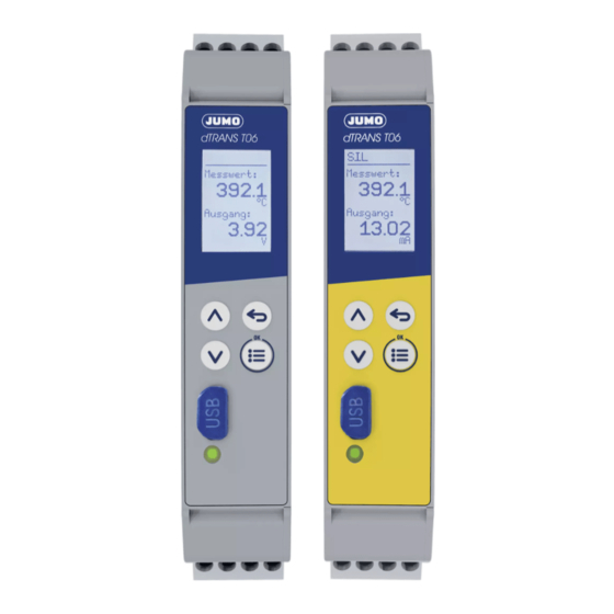
Multifunctional Four-Wire-Transmitter in Mounting Rail Case in Accordance
Brand:
JUMO
| Category:
Transmitter
| Size: 1 MB
Table of Contents
Operating Overwiew
2
Table of Contents
3
1 Brief Description
10
Safety Information
11
2 Identifying the Device Version
12
Scope of Delivery
13
Accessories
14
Device Software Version, Fabrication Number
14
Service Addresses
14
3 Mounting
16
Dimensions
16
Mounting Site, DIN-Rail Mounting
17
Close Mounting
17
Dismounting
18
Galvanic Isolation
19
Use of the USB Interface
19
4 Electrical Connection
20
Installation Notes
20
Connection Diagram
21
Analog Input (Part of the Safety Channel)
22
Analog Output (Part of the Safety Channel)
24
Voltage Supply (on the Nameplate)
24
Extra Codes
25
5 Startup of the Device
26
Display and Control Elements
26
Setting the Display after Device Is Switched on
26
Extra Code SIL
28
Signal Flow
29
6 Safety Manual
32
Brief Description, Intended Use
32
Validity of the Safety Manual
33
Special Operating Statuses
33
Behavior after a Power Failure
33
During Setup Data Transfer
33
After Alteration of the Configuration Level (at the Device or through Setup)
33
Issue of an Error Signal (Safe State)
34
Relevant Standards
34
Connection Possibilities of the Sensors
34
Terms and Abbreviations According to DIN en 61508 and DIN en 61511
35
Safety-Relevant Parameters
38
Failure Rates and SFF for 707071/X - 23/XXX (AC240V)
38
Failure Rates and SSF for 707071/X - 29/XXX (DC24V)
38
Calculation of PFD Avg
39
Determining the Safety Integrity Level (SIL)
41
Safety Integrity of the Hardware
42
Safety-Relevant System Properties
43
Redundant Use of the System
44
Sensor Connection Possibilities
45
Determining the Achieved Performance Level PL
45
Terms and Abbreviations According to Standards Series DIN en ISO 13849
46
Calculations of the DIN en ISO 13849-1 Performance Level - 707071/X - 23/XXX (AC240V)
47
Calculations of the DIN en ISO 13849-1 Performance Level - 707071/X - 29/XXX (DC24V)
47
Risk Reduction through the Control System
48
Other Applicable Device Documentation
49
Behavior During Operation and in Case of Malfunction
49
Regular Tests
49
Proof Test a
50
Proof Test B
51
Proof Test C
56
Recommended Tests for Temperature Probes
57
7 Configuration
60
Overview
60
Device Data
61
Language
61
Unit
61
Language after Power on
61
Display/Operation
62
Normal Display
62
Decimal Place
62
Contrast
62
Lighting
63
Time-Out Lighting
63
Time-Out Operation
63
Code
63
Analog Input
64
Sensor Type
64
Linearization
65
Temperature Difference
66
Temperature Compens
66
Resistance Measuring Range
66
Line Resistance
66
Sensor Factor
66
Resistance Rx
67
Line Resistance RL
67
Resistance R0
67
Resistance RA, RS and RE
68
Scaling Start
68
Scaling End
68
Offset
68
Fine Calibration Start Actual
68
Fine Calibration End Actual
68
Fine Calibration Start Target
68
Fine Calibration End Target
68
Noise Suppression
68
Analog Output
69
Signal Type
69
Output Range Start
69
Output Range End
69
Filter Time Constant
69
Scaling Start
70
Scaling End
70
Reversion Output
70
Error Signal
70
Response for Limit Error
70
Signal from Diagnosis Error
70
Simulation Output
71
Simulation Value
71
Behavior When Leaving the Scaling Range
72
Limit Value Monitoring
73
Function
73
RS485 Interface
74
Baud Rate
74
Limit Value
74
Switch Difference
74
Switching Behavior
74
Switch on Delay
74
Switch off Delay
74
Service
75
Minimum Meas. Value
75
Maximum Meas. Value
75
Min.value Reset
75
Max.value Reset
75
Switching Cycle Limit
75
Data Format
75
Device Address
75
Current Switching Cycles
76
8 Device Info
77
Version
77
Service
78
Operating Hours Total
78
Operating Hours Since Last Configuration
78
Hardware Recognition
78
9 Technical Data
80
Analog Input
80
RTD Temperature Probe
80
Thermocouples
82
Standard Signals
83
Resistance Transmitter
84
Resistance/Potentiometer
85
Measuring Circuit Monitoring
85
Test Voltages
86
Electrical Safety
86
Analog Output
86
Relay Output (Extra Code)
87
Display
87
Electrical Data
88
Environmental Influences
88
Housing
88
Approvals/Approval Marks
89
10 Setup Program
90
Minimum Hardware and Software Requirements
90
Displaying the Device Software Version
90
Forgotten the Code
91
Customer-Specific Linearization
91
Reset Drag Indicator
92
Switch on / Switch off SIL Extra Code
93
Checking of Safety Relevant System Settings
93
11 Error Messages
94
Display Types
94
Safety Channel
95
Diagnostics Channel
97
Measured Value Recording
99
12 What to Do, if
100
13 Certificates
104
China Rohs
109
Advertisement
Advertisement
Related Products
JUMO dTRANS T06 Ex
Jumo dTRANS T05
Jumo dTRANS T01 HART
JUMO dTRANS T02 PCP
JUMO dTRANS T08 12
JUMO dTRANS T08 37
JUMO dTRANS T08 31
JUMO dTRANS T04
JUMO dTRANS T02 Ex
JUMO dTRANS T03 J
JUMO Categories
Transmitter
Measuring Instruments
Controller
Thermostat
Voice Recorder
More JUMO Manuals
Login
Sign In
OR
Sign in with Facebook
Sign in with Google
Upload manual
Upload from disk
Upload from URL