Sign In
Upload
Manuals
Brands
JRC Manuals
Marine Radar
JMA-5330-12
JRC JMA-5330-12 Manuals
Manuals and User Guides for JRC JMA-5330-12. We have
2
JRC JMA-5330-12 manuals available for free PDF download: Instruction Manual, Operation And Quick Indication
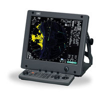
JRC JMA-5330-12 Instruction Manual (440 pages)
Brand:
JRC
| Category:
Marine Radar
| Size: 7 MB
Table of Contents
Precautions before Operation
2
First-Aid Treatments
3
When Pulse Is Beating but Breathing Has Stopped
4
When both Pulse and Breathing Have Stopped
5
Preface
6
Warning Label
7
Before Operation
7
Precautions
8
Equipment Appearance
16
Table of Contents
18
Attached Drawing
24
Glossary
25
Specification
27
General and Equipment Composition
28
Functions
29
1.1.1 Function of this System
29
Features
30
Various Functions
31
Configuration
32
Scanner Unit
32
Exterior Drawings
33
Exterior Drawing
34
General System Diagrams
42
General System Diagrams
44
Names and Functions of Control Panel Switches and Functions of Software Buttons
48
Names and Functions of Control Panel Switches
49
Functions of Software Buttons
55
RADAR Menu
61
Display Info
62
Basic Operation
64
Flow Operation
65
Power on and Start the System
66
Observe and Adjust Video
67
Acquire and Measure Data
67
End the Operation and Stop the System
68
Menu Composition
69
Overview of Menu Structure
69
Basic Menu Operation
70
Preparation
72
Adjust Display Brilliance
72
Adjust Contrast
72
Adjust Operation Panel Brilliance [Panel]
73
Switch Day/Night Mode [Day/Night]
73
Adjust Brilliance of Information on Radar Display (Brilliance Setting)
74
Adjust Sound Volume (Buzzer Volume)
75
Reset Alarm Buzzer [Alarm Ack]
75
Set Display Color
76
Basic Operations
79
Start Transmission [Tx/Prf]
79
Stop Transmission [Stby]
79
Change Range (Observation Range Scale) [Range+/-]
79
Tune
80
Control Sensitivity [Gain/Pl]
80
Suppress Sea Clutter [Auto-Sea]
81
Suppress Rain/Snow Clutter [Auto-Rain]
83
Reject Radar Interference [Ir]
85
Hide/Display Range Rings (Rings)
86
Hide Ship's Heading Line (Hl Off)
86
Hide Graphics Information on Radar Display (Graphic Display)
87
General Operations
88
Move Cross Cursor Mark by Trackball
88
Use Ebls (Electronic Bearing Lines) [Ebl1/2]
89
Set Ebl Operation (Ebl1 /2 Setting)
91
Display Variable Range Markers [Vrm1/Vrm2]
94
Display Parallel Index Lines (Parallel Index Line)
97
Switch Bearing Display Mode [Azi Mode]
105
Switch True/Relative Motion Display Mode [Tm/Rm]
106
Move Own Ship's Display Position [Off Cent]
107
Display Other Ships' Trails [Trails]
108
Trails Motion Mode
109
Switch Pulse Length (Gain/Pl)
111
Expand Targets (Target Enhance)
112
Use Video Process (Process)
113
Zoom
114
Use Marker [Mob]
115
Marking [Mark]
116
Operate Ebl Maneuver Function (Ebl Maneuver)
117
Operate Multi-Function Control [Multi]
120
Operate User Key Switches [User Key 1/2]
122
Operation of Guard Zone [Ata Guard Zone]
124
Radar Alarm (Radar Alarm)
127
Sensitivity Level
127
Display Own Ship's Track
131
Display Own Ship's Track (Display Own Track)
131
Set Own Ship's Track Data Storage Interval (Own Track Interval)
132
Clear Own Ship's Track Data (Clear Own Track)
133
Cancel Storing of Own Ship's Track Data (Own Track Memory)
134
Display Charts
135
Display Coastline Rom Card Produced by Jrc
135
Display Erc Card
136
Display Chart
136
Fill Charts (Fill Land Area)
137
Display Navigation Information
138
Display Waypoint Marks (Waypoint Display)
138
Display Navigation Information (Nav Display Setting)3-75
139
Create/Edit Navigation Information (Edit User Map)
140
Set Navigation Information (User Map Setting)
146
Set and Display Geodetic System
153
Operate Performance Monitor (Pm Display)
155
Operation Procedures
155
Preparation for Operation
155
Check Procedure
157
Applied Operations
161
Set Radar Signal Processing (Process Setting)
161
Set Radar Trails (Radar Trails Setting)
164
Set Cursor (Cursor Setting)
166
Set Screen
167
Depth Range
170
Time Table
170
Set Scanner (Trx Setting)
171
Band Select
172
Set Chart Display (Map Setting)
173
Grid Display
177
Map Shift
180
Set Loran C (Loran C Correction)
183
Use Function Switch [Func]
184
Operation Procedures
184
Function Setting Menu Items
185
Overview of Function Operations
186
Overview of Stored Function Setting Data
189
Personal Information (Pin Setting)
190
Using Card
193
Save in and Transfer to Card (Mem Capa/Copy)
193
Erase/Initialize Card Memory (Clr Mem Init Card)
197
Measurement of Range and Bearing
200
Measurement by Trackball
202
Measurement by Range Rings
203
Measurement by Ebls and Vrms
204
Measurement between Two Optional Points
206
Preparation
211
Collision Avoidance
213
Basic Concept of Collision Avoidance
214
Relative Vector and True Vector
214
Definitions of Symbols
216
Setting Collision Decision Criteria (Cpa/Tcpa Limit)
218
Setting Vectors (Vector Time)
219
Setting Cpa Ring (Cpa Ring)
220
Setting Automatic Acquisition Key Assignment (Gz Alarm Key Setting)
221
Epa Operation
222
Plotting Targets
222
Modifying Plotted Target Data
223
Canceling Plotted Target Data
223
Displaying Numeric Data of Plotted Targets
224
Setting Epa Alarm (Audible Warning)
225
Ata/Arpa Operation
226
Acquiring Target
226
Automatic Acquisition [AUTO]
226
Manual Acquisition [MANUAL]
227
Canceling Unwanted Targets
228
Displaying Target ID No. (Target Number Display)
229
Ata/Arpa Data Display
230
Display of Vectors
230
Display of Past Positions [PAST POSN]
233
Target Data Display
235
Alarm Display
239
Guard Zone Alarm
240
Lost Target Alarm
241
System Function Alarm
242
Gyro Set Alarm
242
Trial Maneuvering (Trial)
243
Trial Maneuvering in the True Vector Mode
244
Executing the TRIAL Function
246
Ata/Arpa Simulation
247
Target Speed
249
Setting Ata/Arpa Tracks (Ata Track Setting)
253
Ais Operation
260
Initial Setting
261
TCPA Limit
262
Setting Ais Display Function (Ais Function)
263
Activating Ais Targets
264
Manual Activation
264
Automatic Activation
264
Deactivating Ais Targets
265
Setting Ais Symbol Display Function (Ais Symbol Display)
266
Displaying Numeric Data of Ais Targets
267
Setting Ata/Arpa Symbol Display Function (Ata Symbol Display)
269
Setting Ais Filter (Ais Filter Setting)
270
Deciding Ais Target and Arpa Target as the same One (Identical Distance)
273
Conditions for Deciding Ais Target to be Lost
275
Displaying Ais Symbols
276
Ais Alarm Display
277
Restrictions
278
True and False Echoes on Display
279
Radar Wave with the Horizon
281
Strength of Reflection from the Target
283
Sea Clutters
284
False Echoes
285
Display of Radar Transponder (Sart)
288
Maintemance
290
Routine Maintenance
292
Maintenance on each Unit
293
Scanner Unit NKE-2102/2252/1075
293
Precautions in Mounting the Cover
294
Display Unit NCD-4510
299
Trouble Shooting and Adjustment
301
Performance Check
302
Check Performance on Test Menu
303
Flash Rom
305
Sensor Test
306
Key Check
310
Error Logging
314
List of Alarms and Other Indications
320
Fault Finding
322
Trouble Shooting
323
Replacement of Major Parts
328
Parts Required for Periodic Replacement
329
Replacement of Magnetron (V1/V201)
329
Replacement of LCD Monitor
330
Adjustments
331
Tuning Adjustment
333
Bearing Adjustment
334
Range Adjustment
335
Antenna Height Adjustment
336
Bearing Pulse Output Adjustment (Output Pulse)
337
COM Port Setting
340
Antenna Location
346
Language Setting (Language)
349
Vector Constant
357
Main Bang Suppression Level Adjustment (MBS Level)
359
Adjustment of NSK Unit to GYRO Compass and Log
361
Setting
363
Ship Speed Equipment Setting (Speed Equipment)
364
Manual Speed Setting (Manual Speed)
365
MAG Compass Setting
366
Correct Value
366
Current Correction (SET/DRIFT) Setting
367
List of Geodetic Systems
372
DGPS Mode
378
GPS Reception Status Display (GPS Status)
387
Fix Mode
389
Date/Time Setting
390
Enter the Date
390
Adjustment of Performance Monitor (NJU-63/64)
392
After-Sales Service
395
When You Request for Repair
396
Recommended Maintenance
396
Radar Failure Check List
397
Disposal
400
Disposal of the Unit
400
Disposal of Used Batteries
401
Disposal of Used Magnetron
402
Jma-5310-6 Type Radar
404
Jma-5320-7/9 Type Radar
405
Jma-5330-12 Type Radar
406
Scanner (Nke-2102)
407
Scanner (Nke-2252)
408
Scanner (Nke-1075)
409
Display Unit(Ncd-4510)
410
Processor Unit(Ndc-1273)
411
Plotter Unit
413
Arpa-1 (High Performance Arpa)
415
Arpa-2 (Normal Edition Ata)
416
Keyboard Unit
417
Keyboard Unit(Nce-7699)
417
Input Enable Signal
418
Output Enable Signal
419
Standard Configuration
420
Equipment Distance between Instruments
421
Equipment Distance between Other Instruments
421
Others (Option)
422
Advertisement
JRC JMA-5330-12 Operation And Quick Indication (6 pages)
Brand:
JRC
| Category:
Marine Radar
| Size: 0 MB
Table of Contents
State-Of-The-Art Radar Technology "Real-Time Radar"
2
JMA-5300 Series - Developed for Maximum Ease of Use
3
Display NWZ-147
4
Unique Features
5
Chart Overlay
5
JMA-5300 Series - Performance Features
5
Jma-5300 Specifications
6
Advertisement
Related Products
JRC JMA-5332-12
JRC JMA-5322-9
JRC JMA-5312-6HS
JRC JMA-5322-7
JRC JMA-5312-6
JRC JMA-5322-6HS
JRC JMA-5310-6
JRC JMA-5312-6/6HS
JRC JMA-5362-8R
JRC JMA-5320-7
JRC Categories
Marine Radar
Water Filtration Systems
Marine Equipment
Receiver
Radio Parts
More JRC Manuals
Login
Sign In
OR
Sign in with Facebook
Sign in with Google
Upload manual
Upload from disk
Upload from URL