Sign In
Upload
Manuals
Brands
Johnson Controls Manuals
Inverter
VS3-349D0DN-C21C
Johnson Controls VS3-349D0DN-C21C Manuals
Manuals and User Guides for Johnson Controls VS3-349D0DN-C21C. We have
1
Johnson Controls VS3-349D0DN-C21C manual available for free PDF download: Applications Manual
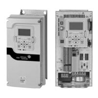
Johnson Controls VS3-349D0DN-C21C Applications Manual (244 pages)
Variable Speed Drive
Brand:
Johnson Controls
| Category:
Inverter
| Size: 4.63 MB
Table of Contents
Table of Contents
4
Before Commencing the Installation
15
Definitions and Symbols
16
Hazardous High Voltage
16
Warnings and Cautions
16
Important Safety Information
17
Chapter 1-Variable Speed Drives Series III Overview
25
How to Use this Manual
25
Receiving and Inspection
25
Real Time Clock Battery Activation
25
Figure 1. RTC Battery Connection
25
Table 1. Common Abbreviations
25
Rating Label
26
Carton Rating Label
26
Figure 2. VS3 Rating Label
26
Figure 3. VS3 Carton Rating Label
26
Catalog Number System
27
Figure 4. Johnson Controls Series III VSD-Catalog Numbering System
27
Power Ratings and Product Selection
28
Table 2. Open Type /IP20
28
Table 3. Type 1/IP21
28
Table 4. Type 12/IP54
28
Table 5. Open Type /IP20
29
Table 6. Type 1/IP21
29
Table 7. Type 12/IP54
30
Table 8. Type 1/IP21
30
Table 9. Type 12/IP54
31
Chapter 2-Keypad Overview
32
Overview
32
Figure 5. Keypad and Display
32
Keypad Buttons
33
Table 10. Keypad Buttons
33
LED Lights
35
LCD Display
35
Figure 6. General View of LCD
35
Figure 7 . Welcome Page
35
Table 11. LED State Indicators
35
Figure 8. Upgrade Page
36
Figure 9. Auto Backup Page
36
Figure 10. Main Menu
36
Table 12. Soft Keys
36
Figure 11. Parent Node Page
37
Figure 12. Parameter Page
37
Figure 13. Parameter Page from Favorite Menu
37
Figure 14. Fault Page
37
Chapter 3-Menu Overview
38
Main Menu Page
38
Menu Navigation
38
Figure 15. Main Menu Page
38
Figure 16. Main Menu Navigation
38
Menu Structure
39
Table 13. Keypad Menus
39
M - Monitor
40
Figure 17 . M-Monitor
40
F - Fault
41
Figure 18. Active Faults
41
Pop-Up Fault
42
Figure 19. Pop-Up Active Faults
42
Fault History
43
Figure 20. Fault History
43
Fault Log
44
P - Parameter
44
Figure 21. Parameter Setting
44
Figure 23. down from Keypad
46
Figure 24. Parameters Comparison
47
Figure 25. Password
48
Value Edit
49
Figure 26. Edit Parameter Value
49
T-Favorite
50
Figure 27 . Parameter Locked
50
Chapter 4-Startup
51
Startup Wizard Page
51
Startup Wizard
51
Table 14. Startup Wizard Instructions
51
PID and Advanced Application Mini-Wizard
52
Table 14. Startup Wizard Instructions Continued
52
Table 15. PID Mini-Wizard Values
52
Chapter 5-Basic Application
53
I/O Controls
53
Force Open/Force Close Selection
54
DIGIN Selection
54
Option Board Digin Selection
54
Basic Application Control I/O Configuration
55
CHAPTER 5-BASIC APPLICATION, Continued
55
Table 16. I/O Connection
55
Table 17. Drive Communication Ports
56
Basic Application-Parameters List
57
Control I/O Configuration
57
Monitor
57
Table 18. Basic-M1
57
Table 19. IO Status-M2
57
Table 20. Optional Boards - M3
58
Table 21. Energy Savings - M4
58
Table 22. FB Monitor Menu - M5
58
Table 22. FB Monitor Menu - M5 Continued
59
Table 23. User Defined Output - M8
59
Table 24. MWH Monitor - M9
59
Parameters
60
Table 25. Multi-Monitoring - M10
60
Table 26. Basic Parameters - P1
60
Inputs
61
Table 27. Basic Setting - P2.1
61
Table 28. Digital Input - P2.2
61
Table 28. Digital Input - P2.2, Continued
62
Table 29. Preset Speed - P2.3
63
Table 30. AI1 Settings - P2.4
63
Table 31. AI2 Settings - P2.5
63
Outputs
64
Table 32. Digital Output - P3.1
64
Table 32. Digital Output - P3.1 Continued
65
Table 33. Supervisions - P3.2
65
Table 33. Supervisions - P3.2 Continued
66
Table 34. Analog Output 1 - P3.3
66
Table 35. Analog Output 2 - P3.4
66
Drive Control
67
Table 36. Basic Setting - P4.1
67
Table 37. Brake - P4.2
67
Table 38. Skip Frequency - P4.3
67
Motor Control
68
Protections
68
Table 39. Analog Output 2 - P3.4
68
Table 40. Basic Setting - P5.1
68
Table 41. Motor - P6.1
68
Table 42. Drive - P6.2
70
Table 43. Communication - P6.3
70
Table 44. Auto Restart - P6.4
71
Table 45. Fire Mode - P9
71
Table 46. Basic Setting - P10.1
71
Communication
72
Table 47. FB Process Data Input Sel - P12.1
72
Table 48. FB Process Data Output Sel - P12.2
72
RS485 Bus
73
Table 49. Basic Setting - P12.3.1
73
Table 50. Modbus RTU - P12.3.2
73
Ethernet Bus
74
Table 51. Bacnet MS/TP - P12.3.3
74
Table 52. SA Bus - P12.3.4
74
Table 53. Basic Setting - P12.4.1
74
Table 54. Modbus TCP - P12.4.2
74
Figure 22. Parameter Sets
75
System
75
Table 55. Bacnet IP - P12.4.3
75
Table 56. Basic Setting - P13.1
75
Table 57. Version Info - P13.2
77
Table 58. Application Info - P13.3
77
Table 59. User Info - P13.4
77
Table 60. Operate Mode - O
77
Chapter 6 - Pid Application
78
Introduction
78
I/O Controls
78
Force Open/Force Close Selection
79
DIGIN Selection
79
Option Board Digin Selection
79
Timer Channel Selection
79
Control I/O Configuration
80
Table 61. PID Application Default I/O Connection
80
PID Application-Parameters List
81
Table 62. Drive Communication Ports
81
Table 63. Basic - M1
82
Table 64. IO Status - M2
82
Table 65. Optional Boards - M3
82
Table 66. Energy Savings - M4
82
Table 67. FB Monitor Menu - M5
83
Table 68. PID Monitor - M6
84
Table 69. Timer/Interval Control - M7
85
Table 70. User Defined Output - M8
85
Table 71. MWH Monitor - M9
85
Table 72. Multi-Monitoring - M10
85
Parameters
86
Inputs
86
Table 73. Basic Parameters - P1
86
Table 74. Basic Setting - P2.1
86
Table 75. Digital Input - P2.2
87
Table 76. Preset Speed - P2.3
89
Table 77. AI1 Settings - P2.4
89
Table 78. AI2 Settings - P2.5
89
Outputs
90
Table 79. Digital Output - P3.1
90
Table 80. Supervisions — P3.2
91
Table 81. Analog Output 1 - P3.3
92
Drive Control
93
Table 82. Analog Output 2 - P3.4
93
Table 83. Basic Setting - P4.1
93
Table 84. Brake - P4.2
94
Table 85. Skip Frequency - P4.3
94
Table 86. Energy Savings Calc - P4.4
94
Motor Control
95
Protections
95
Table 87. Basic Setting - P5.1
95
Table 88. Second Motor Parameter - P5.2
95
Table 90. Drive - P6.2
97
Table 91. Communication - P6.3
97
Table 92. Auto Restart - P6.4
97
PID Controller 1
98
Table 93. Basic Setting - P7.1
98
Setpoint
99
Table 94. Monitor - P7.2
99
Table 95. Basic - P7.3.1
99
Table 96. Setpoint 1 - P7.3.2
99
Feedback
100
Table 97. Setpoint 2 - P7.3.3
100
Table 98. Basic - P7.4.1
100
Feedforward
101
Table 99. Feedback 1 - P7.4.2
101
Table 100. Feedback 2 - P7.4.3
101
Table 101. Basic - P7.5.1
101
PID Controller 2
102
Table 102. Feedforward 1 - P7.5.2
102
Table 103. Feedforward 2 - P7.5.3
102
Table 104. Basic Setting - P8.1
102
Setpoint
103
Table 105. Monitor - P8.2
103
Table 106. Basic - P8.3.1
103
Table 107. Setpoint 1 - P8.3.2
103
Feedback
104
Table 108. Setpoint 2 - P8.3.3
104
Table 109. Basic - P8.4.1
104
Table 110. Feedback 1 - P8.4.2
104
Feedforward
105
Table 111. Feedback 2 - P8.4.3
105
Table 112. Basic - P8.5.1
105
Table 113. Feedforward 1 - P8.5.2
105
Table 114. Feedforward 2 - P8.5.3
105
Bypass
106
Table 115. Fire Mode - P9
106
Table 116. Basic Setting - P10.1
106
Real Time Clock
107
Table 117. Redundant Drive - P10.2
107
Table 118. Interval 1 - P11.1
107
Table 119. Interval 2 - P11.2
107
Table 120. Interval 3 - P11.3
107
Communication
108
Table 121. Interval 4 - P11.4
108
Table 122. Interval 5 - P11.5
108
Table 123. Timer - P11.6
108
Table 124. FB Process Data Input Sel - P12.1
108
Table 125. FB Process Data Output Sel - P12.2
109
RS485 Bus
110
Table 126. Basic Setting - P12.3.1
110
Table 127. Modbus RTU - P12.3.2
110
Ethernet Bus
111
Table 128. Bacnet MS/TP - P12.3.3
111
Table 129. Basic Setting - P12.4.1
111
Table 130. Modbus TCP - P12.4.2
111
System
112
Table 133. Version Info - P13.2
114
Table 134. Application Info - P13.3
115
Table 135. User Info - P13.4
115
Table 136. Operate Mode - O
115
Chapter 7-Advanced Application Parameter
116
I/O Controls
116
Force Open/Force Close Selection
117
DIGIN Selection
117
Option Board Digin Selection
117
Timer Channel Selection
117
Control I/O Configuration
118
Table 137. Advanced Application Default I/O Configuration
118
Table 138. Drive Communication Ports
119
Advanced Application-Parameters List
120
Monitor
120
Table 139. Basic - M1
120
Table 140. IO Status - M2
120
Table 141. Optional Boards - M3
121
Table 142. Energy Savings - M4
121
Table 143. FB Monitor Menu - M5
121
Table 144. PID Monitor - M6
122
Parameters
123
Table 145. Timer/Interval Control - M7
123
Table 146. User Defined Output - M8
123
Table 147. MWH Monitor - M9
123
Table 148. Multi-Monitoring - M10
123
Table 149. Basic Parameters - P1
123
Table 150. Basic Setting - P2.1
124
Table 151. Digital Input - P2.2
125
Table 152. Preset Speed - P2.3
127
Table 153. Preset Speed - P2.3
127
Table 154. Preset Speed - P2.3
127
Outputs
128
Table 155. Digital Output - P3.1
128
Table 156. Supervisions - P3.2
129
Table 156. Supervisions - P3.2
130
Table 157 . Supervisions - P3.2
130
Table 158. Analog Output 2 - P3.4
131
Table 159. Logic Function - P3.5
131
Drive Control
132
Table 160. Basic Setting - P4.1
132
Motor Control
133
Table 161. Brake - P4.2
133
Table 162. Skip Frequency - P4.3
133
Table 163. Energy Savings Calc - P4.4
133
Table 164. Basic Setting - P5.1
133
Protections
134
Table 89. Motor - P6.1
134
Table 165. Second Motor Parameter - P5.2
134
Table 166. Motor - P6.1
135
Table 167. Drive - P6.2
136
Table 168. Communication - P6.3
136
Table 169. Auto Restart - P6.4
136
PID Controller 1
137
Table 170. Basic Setting - P7.1
137
Setpoint
138
Table 171. Monitor - P7.2
138
Table 172. Basic - P7.3.1
138
Table 173. Setpoint 1 - P7.3.2
139
Table 174. Setpoint 2 - P7.3.3
139
Feedback
140
Feedforward
140
Table 175. Basic - P7.4.1
140
Table 176. Feedback 1 - P7.4.2
140
Table 177. Feedback 2 - P7.4.3
140
Table 178. Basic - P7.5.1
140
PID Controller 2
141
Table 179. Feedforward 1 - P7.5.2
141
Table 180. Feedforward 2 - P7.5.3
141
Table 181. Basic Setting - P8.1
141
Setpoint
142
Table 182. Monitor - P8.2
142
Table 183. Basic - P8.3.1
142
Table 184. Setpoint 1 - P8.3.2
142
Feedback
143
Table 185. Setpoint 2 - P8.3.3
143
Table 186. Basic - P8.4.1
143
Table 187. Feedback 1 - P8.4.2
143
Table 188. Feedback 2 - P8.4.3
143
Feedforward
144
Table 189. Basic - P8.5.1
144
Table 190. Feedforward 1 - P8.5.2
144
Table 191. Feedforward 2 − P8.5.3
144
Table 192. Fire Mode − P9
144
Bypass
145
Real Time Clock
145
Table 193. Basic Setting - P10.1
145
Table 194. Redundant Drive - P10.2
145
Table 195. Interval 1 - P11.1
145
Table 196. Interval 2 - P11.2
146
Table 197. Interval 3 - P11.3
146
Table 198. Interval 4 - P11.4
146
Table 199. Interval 5 - P11.5
146
Communication
147
Table 200. Timer - P11.6
147
Table 201. FB Process Data Input Sel - P12.1
147
Table 202. FB Process Data Output Sel - P12.2
147
RS485 Bus
148
Table 203. Basic Setting - P12.3.1
148
Table 204. Modbus RTU - P12.3.2
148
Ethernet Bus
149
Table 205. Bacnet MS/TP - P12.3.3
149
Table 206. SA Bus - P12.3.4
149
Table 207. Basic Setting - P12.4.1
149
Table 131. Bacnet IP - P12.4.3
150
Table 208. Modbus TCP - P12.4.2
150
Table 209. Bacnet IP - P12.4.3
150
System
151
Table 132. Basic Setting - P13.1
151
Table 210. Basic Setting - P13.1
152
Table 211. Version Info - P13.2
152
Table 212. Application Info - P13.3
153
Table 213. User Info - P13.4
153
Table 214. Operate Mode - O
153
Appendix A-Description of Parameters
154
Application Level
154
Figure 28. Acceleration and Deceleration Time
154
Figure 29. Motor Parameters from Ratings Plate
155
Figure 30. with and Without Reference Scaling
158
Figure 31. Start Forward/Start Reverse
158
Figure 32. Start, Stop and Reverse
159
Figure 33. Start Pulse/Stop Pulse
160
Figure 34. Start Forward/Start Reverse
161
Figure 35. Start Pulse/Stop Pulse
162
Figure 36. Activation of Fixed Frequencies
166
Figure 37. AI1 2Wire-Current
170
Figure 38. AI1 3Wire-Current
170
Figure 39. AI1 4Wire-Current
171
Figure 40. AI1 Reference Potentiometer 10V
171
Figure 41. Analog Input AI Scaling
171
Figure 42. AI1 Signal Filtering
172
Figure 43. AI1 no Signal Inversion
172
Figure 44. AI1 Signal Inversion
172
Figure 45. Example of Joystick Hysteresis
173
Figure 46. Example of Sleep Limit Function
173
Figure 47. AI2 2Wire-Current
174
Figure 48. AI2 3Wire-Current
174
Figure 49. AI2 4Wire-Current
174
Figure 50. AI2 Differential Voltage
174
Figure 51. AI2 Pot Ref
175
Figure 52. Supervision Function
182
Figure 53. Analog Output Filtering
185
Figure 54. Analog Output Scaling
186
Figure 55. Analog Output Invert
186
Figure 56. Acceleration/Deceleration (S-Shaped)
188
Figure 57. DC-Braking Time When Stop Mode = Coasting
190
Figure 58. DC-Braking Time When Stop Mode = Ramp
190
Figure 59. Example of Skip Frequency Area Setting
192
Figure 60. Linear and Squared Change of Motor Voltage
193
Figure 61. Programmable V/Hz Curve
194
Figure 62. Motor Thermal Current It Curve
196
Figure 63. Motor Temperature Calculation
197
Figure 64. Stall Characteristics Settings
198
Figure 65. Stall Time Count
198
Figure 66. Setting of Minimum Load
199
Figure 67. Underload Time Counter Function
199
Figure 68. Auto Restart Fail (Try Number >2.)
203
Figure 69. Setting up PID Application
207
Figure 70. Setting up PID Application
212
Appendix B- Fault Log
234
Fault Codes and Descriptions
234
Table 215. Active Faults
234
Table 216. History Faults
234
Appendix C-Recommended Secure Hardening Guidelines
239
Introduction
239
Secure Configuration Guidelines
239
Advertisement
Advertisement
Related Products
Johnson Controls VS3-349D0DN-C54C
Johnson Controls VS3-343D3DN-C21C
Johnson Controls VS3-344D3DN-C21C
Johnson Controls VS3-347D6DN-C21C
Johnson Controls VS3-34023DN-C21C
Johnson Controls VS3-34038DN-C21C
Johnson Controls VS3-34061DN-C21C
Johnson Controls VS3-34205DN-C21C
Johnson Controls VS3-34170DN-C21C
Johnson Controls VS3-34310DN-C21C
Johnson Controls Categories
Controller
Air Conditioner
Thermostat
Control Unit
Irrigation System
More Johnson Controls Manuals
Login
Sign In
OR
Sign in with Facebook
Sign in with Google
Upload manual
Upload from disk
Upload from URL