Sign In
Upload
Manuals
Brands
Johnson Manuals
Radio
5300 Series
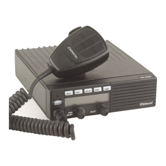
User Manuals: Johnson 5300 Series Mobile Radio Kit
Manuals and User Guides for Johnson 5300 Series Mobile Radio Kit. We have
1
Johnson 5300 Series Mobile Radio Kit manual available for free PDF download: Service Manual
Johnson 5300 Series Service Manual (239 pages)
Brand:
Johnson
| Category:
Radio
| Size: 21 MB
Table of Contents
Table of Contents
3
General Information
7
Scope of Manual
7
Transceiver Description
7
General
7
Analog/Digital Operation
7
Operating Protocols
7
Available Mounting Options
8
Systems, Channels, and Zones
8
Programming
8
Alignment
8
Product Warranty
9
Model Number Breakdown
9
Identification Label Example
9
Serial Number Breakdown
10
Accessories
10
Factory Customer Service
11
Returns for Repairs
12
Replacement Parts
12
Internet Home Page
13
Secure Communication
13
General
13
FIPS 140-2 Approved Encryption
13
Over-The-Air-Rekeying (OTAR)
13
Key Retention
13
Radio Hardware Changes
14
RF Module Changes
14
Hardware Changes Flowchart
14
Logic Board Changes
15
53Xx Firmware/Logic Board Versions
15
5300 Series Mobile Specifications
17
Revision Summary
18
Installation
22
Front Mount Installation Components
24
Important Digital Radio Installation Information
22
Introduction
22
Installation Guidelines
22
General Information
24
Scope of Instructions
24
Performance Tests
24
Transceiver Programming
24
Transceiver Mounting Bracket
24
Power Source
25
Transceiver Installation (Front and Remote Mount)
25
Mounting Configurations
25
Selecting a Mounting Location
25
Mounting Kits
25
Mounting Standard Power Transceiver
27
Mounting 100W Transceiver
27
Power Cable Installation
27
Standard Models (All Except 100W)
27
Models
28
Accessory Cable Installation
29
General
29
Ignition Sense Input (Pin 6)
29
Speaker Pins (Pins 1, 2, 3)
29
Accessory Jack
29
Auxiliary B out (Pin 4)
30
External Public Address (Pin 7)
30
Auxiliary B Input (Pin 8)
30
Installation
30
2.6 Remote Control Unit
30
Horn Circuit Example
30
General
31
Control Unit Board Versions
31
Revised Display Controller Board
31
Unrevised Display Controller Bd
31
Control Unit DIP Switch S1 Settings
32
Setting Master/Slave Switches
33
Configuring Volume Control
33
Mounting Remote Control Unit
33
Connecting the Speaker
33
Using Standard Internal Speaker
33
Using an Optional External Speaker
34
53Xx Mobile Pigtail Cable Guide
34
Key Cap Installation
34
Pigtail Cables
34
Locking Tray Installation Diagram
35
Transceiver Mounting Tray
35
Installation
35
Description
35
Locking/Unlocking Transceiver
35
Handheld Control Unit
36
Installation
36
General
36
Installation Instructions
37
Using HHC to Provide Dual Controls or Dual Remotes
38
Transceiver Programming with HHC
38
Siren Option Installation
39
Instructions
39
General
39
Transceiver Programming
39
Installation Procedure
39
Operation
41
General
41
Transceiver Programming
42
General
42
Programming Setup
42
Computer Description
42
Connecting Computer to Transceiver
42
Handheld Controller Programming Setup
43
Siren Programming
43
Using the Pcconfigure Software
43
Circuit Description
44
General Transceiver Description
44
Introduction
44
PC Boards
44
Circuit Protection (Fuses)
44
Analog Mode Description
44
Project 25 Digital Mode
45
Uhf Rf Board (Version C)
45
Receiver
45
UHF RF Board Block Diagram (Version C)
46
Synthesizer
47
Transmitter
47
RF Board Block Diagram (Version A/B)
48
Version A/B Rf Board Overview
48
LO and First if Frequencies
49
Antenna Switch
50
Receiver Front End
50
Receiver Back End
51
Transmitter
51
Vhf/Uhf Rf Board (Version A/B)
49
Frequency Generation Unit (FGU)
49
800 Mhz RF BOARD (VERSION A/B)
52
Frequency Synthesis
52
Antenna Switch
53
Receiver Front End
54
Receiver Back End
54
Transmitter
55
Vhf 50W Pa Board
55
Antenna Switches
55
Amplifiers (Q509, Q510)
56
Power Control
56
VHF 50W PA Board Block Diagram
56
Vhf 100W Pa Board
57
Uhf 15W Pa Board
58
Antenna Switches
58
Amplifiers (Q509, Q508)
58
UHF 15W PA Board Block Diagram
58
Power Control
59
Uhf 40W Pa Board
60
Variable Attenuator
60
Driver (Q1), Finals (Q10)
60
UHF 40W PA Board Block Diagram
60
Forward Power Detector, Antenna Switch, Low-Pass Filter
61
Power Control
61
800 Mhz 35W PA BOARD
62
Low Power Antenna Switch
62
Power Detector and Attenuator
62
Power Amplifier Module (U504), Final (Q509)
63
High Power Antenna Switch
63
Directional Coupler, Low-Pass Filter
63
Temp Sense
63
Power Control
64
RF Amplifier (Q503)
64
DC Power Distribution
65
Power on Operation
65
Power off Operation
65
Logic Board (Version C)
65
Microcontroller (U2)
65
Memory
65
Digital Signal Processing Overview
65
Receive Signal Path
66
Alignment Procedure
67
Alignment Setup
67
Pctune Version Required
68
General
67
Introduction
67
Tune Software
67
Main Screen
68
Pctune Main Screen
68
Menu Bar Description
69
File Menu
69
Radio Menu
69
Transfer Menu
69
Tools Menu
70
Help Menu
70
Tuning Procedure
70
Connecting Test Setup
70
Starting and Configuring Pctune
71
Digital Performance Tests
71
General
71
Receive Test Setup
71
Receive Sensitivity Test
71
RPI Front Panel
71
Transmitter Tests
72
Analog Performance Tests
72
General
72
Receiver Performance Tests
72
Transmitter Performance Tests
73
Parts List
74
Chassis, Hardware, and Miscellaneous
74
Interface Board (Ver A/B)
75
Interface Board (Ver C)
75
Receiver/Exciter Assembly (Version A/B)
76
UHF Rx/Exciter Assembly (Version C)
77
VHF 50W PA Board Assembly
78
VHF 100W PA Board Assembly
81
UHF 15W PA Board Assembly
82
UHF 40W PA Board Assembly
85
800 Mhz PA Board Assembly
88
Logic Board Assembly (ARM, Ver A)
92
Front Panel Assembly
111
Display Controller Board (Revised)
111
Display Controller Board (Unrev.)
113
Remote Control Unit Unique Parts
115
Std. DC Power Cable Assembly
116
DC Power Cable Assembly
116
Accessory Wire Harness Kit
116
Front Mounting Bracket Assembly
116
Amplified Dynamic Microphone
116
Watt, 4.0-Ohm Speaker (Black)
117
Watt, 4.0-Ohm Motorcyle Speaker
117
Handheld Control Unit
117
Siren Controller Kit
121
Remote Prog. Interface (RPI)
122
Pigtail Cable EMI Board
122
Mechanical Views
123
Chassis Assembly
123
Remote Control Unit/Transceiver Assembly
124
Receiver/Exciter Assembly (A300)
125
Display Assembly (A713)
126
Front Panel Assembly (A102)
126
100-Watt PA Assembly
127
Handheld Control Unit Junction Box
128
Handheld Control Unit (Part 1 of 2)
128
Handheld Control Unit (Part 2 of 2)
129
Photos
130
Schematic Diagrams and Component Layouts
130
Transceiver Top View
130
Transceiver Bottom View
130
Receiver/Exciter Assembly
131
Front Panel Assembly
131
Amplified Dynamic Microphone
133
Interconnect Schematic
133
Interface Board Schematic (Ver A/B)
135
Interconnect Board (Ver A/B)
136
Schematic (Ver C)
139
Interconnect Board (Ver C)
139
Accessory Pigtail Cable EMI Board
139
Schematic
144
Board Layout
145
VHF RF Board (Ver B)
146
Schematic
146
Board Layout
147
VHF 50W PA Board
147
Board Top View
157
Board Bottom View
158
Schematic
159
Board Layout
160
Board Layout Top View
167
Board Layout Bottom View
168
Board Layout
172
Schematic
175
VHF 100W PA Board
175
Board Bottom View
179
Board Top View
183
PPC Logic Board (Ver B)
185
PPC Logic Board (Ver C)
185
Board Bottom View
200
Display Controller Board
206
Display Board
206
Schematic
206
Remote Transceiver Interconnect Schematic
206
Handheld Control Unit (HHC) Interconnect Schematic
209
Junction Box Schematic
209
Remote Programming Interface (RPI)
214
Bottom View
229
Top View
229
Advertisement
Advertisement
Related Products
Johnson Vintage 50
Johnson 5 HORSEPOWER
Johnson 5.9AE
Johnson JPS Generator 5100
Johnson LTR 8640
Johnson LTR 8644
Johnson LTR 8655
Johnson Categories
Laser Level
Refrigerator
Measuring Instruments
Air Conditioner
Fan
More Johnson Manuals
Login
Sign In
OR
Sign in with Facebook
Sign in with Google
Upload manual
Upload from disk
Upload from URL